Trip le -Ou t p u t P o w e r-S u p p ly
Co n t ro lle r fo r No t e b o o k Co m p u t e rs
MAX782
The major loss mechanisms under heavy loads are, in
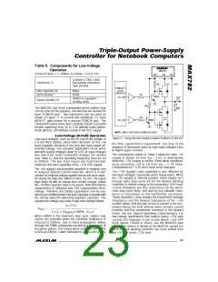
Table 4. Surface-Mount Components
usual order of importance:
2
Factory FAX
● I R losses
Company
USA Phone
[country code]
● gate-charge losses
● diode-conduction losses
● transition losses
● capacitor-ESR losses
Central Semi
Coiltronics
IRC
[ 1] (516) 435-1824 (516) 435-1110
[ 1] (407) 241-9339 (407) 241-7876
[ 1] (213) 772-9028 (512) 992-7900
● losses due to the operating supply current of the IC.
Murata-Erie
Nihon
Siliconix
Sprague
Sumida
[ 1] 404 736-3030
[81] 3-3494-7414
[ 1] (408) 727-5414 (408) 988-8000
[ 1] (603) 224-1430 (603) 224-1961
[81] 3-3607-5144
[81] 3-3278-5358
[ 1] 702 831-3521
(404) 736-1300
(805) 867-2555
Ind uc tor c ore los s e s a re fa irly low a t he a vy loa d s
because the inductor current’s AC component is small.
Therefore, they are not accounted for in this analysis.
Effic ie nc y = P
/P x 100% = P
OUT IN
/(P
+
OUT
OUT
(708) 956-0666
(708) 803-6100
(702) 831-0140
PD ) x 100%
TOTAL
TDK
2
PD
= PD
PD
+ PD
+ PD
+ PD
DIODE TRAN
+
TOTAL
(I R)
GATE
Transpower Tech.
+ PD
CAP
IC
2
2
PD
= resistive loss = (I
) x (R
+ r
+
(I R)
LOAD
COIL
DS(ON)
R
CS
)
where R
is the DC resistance of the coil, r
is
COIL
DS(ON)
the drain-source on resistance of the MOSFET, and
__________Ap p lic a t io n s In fo rm a t io n
R
is the current-sense resistor value. Note that the
CS
r
te rm a s s ume s tha t id e ntic a l MOSFETs a re
DS(ON)
Effic ie n c y Co n s id e ra t io n s
Achieving outstanding efficiency over a wide range of
loads is a result of balanced design rather than brute-
force overkill, particularly with regard to selecting the
power MOSFETs. Generally, the best approach is to
design for two loading conditions, light load and heavy
load (corresponding to suspend and run modes in the
host computer), at some nominal battery voltage (such
as 1.2V/cell for NiCd or NiMH). Efficiency improves as
the input voltage is reduced, as long as the high-side
switch saturation voltage is low relative to the input volt-
age. If there is a choice, use the lowest-voltage battery
pack possible, but with at least six cells.
employed for both the synchronous rectifier and high-
side switch, because they time-share the inductor cur-
rent. If the MOSFETs are not identical, losses can be
e s tima te d b y a ve ra g ing the two ind ivid ua l r
terms according to duty factor.
DS(ON)
PD
= gate driver loss = q x f x VL
G
GATE
where VL is the MAX782’s logic supply voltage (nomi-
nally 5V) and q is sum of the gate charge for low-
G
side and high-side switches. Note that gate charge
los s e s a re d is s ip a te d in the IC, not the MOSFETs ,
and therefore contribute to package temperature rise.
For matched MOSFETs, q is simply twice the gate
G
charge of a single MOSFET (a data sheet specifica-
tion). If the +5V buck SMPS is turned off, replace VL
Heavy-Load Efficiency
Losses due to parasitic resistances in the switches,
coil, and sense resistor dominate at high load-current
levels. Under heavy loads, the MAX782 operates in the
continuous-conduction mode, where there is a large
DC offset to the inductor current plus a small sawtooth
AC component (see the +3.3V Inductor section). This
DC current is exactly equal to the load current – a fact
that makes it easy to estimate resistive losses through
the assumption that total inductor current is equal to
this DC offset current.
in this equation with V
.
IN
P
= diode conduction losses = I x V x t x f
LOAD D D
DIODE
whe re t is the d iod e ’s c ond uc tion time (typ ic a lly
D
110ns), V is the forward voltage of the Schottky diode,
D
and f is the switching frequency.
2
V
IN
x C
x I
LOAD
x f
RSS
PD
= transition loss = ———————————
TRAN
I
DRIVE
______________________________________________________________________________________ 19

 MAXIM [ MAXIM INTEGRATED PRODUCTS ]