Trip le -Ou t p u t P o w e r-S u p p ly
Co n t ro lle r fo r No t e b o o k Co m p u t e rs
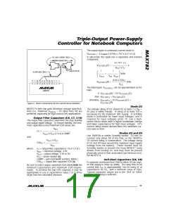
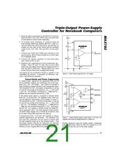
Because this ramp is applied to the current-limit circuit,
the a c tua l time for the outp ut volta g e to ra mp up
d e p e nd s on the loa d c urre nt a nd outp ut c a p a c itor
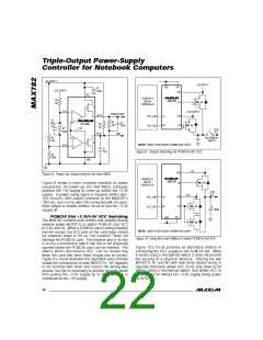
value. Using Figure 1’s circuit with a 2A load and no
SS c a p a c itor, full outp ut volta g e is re a c he d a b out
600µs after ON_ is driven high.
Byp a s s Ca p a c it o rs
Input Filter Capacitors (C1, C13)
Use at least 3µF/W of output power for the input filter
capacitors, C1 and C13. They should have less than
150mΩ ESR, and should be located no further than
10mm from N1 and N2 to prevent ringing. Connect
the ne g a tive te rmina ls d ire c tly to PGND. Do not
e xc e e d the s urg e c urre nt ra ting s of inp ut b yp a s s
capacitors.
Bo o s t Ca p a c it o rs (C4 , C5 )
Capacitors C4 and C5 store the boost voltage and pro-
vide the supply for the DH3 and DH5 drivers. Use 0.1µF
and place each within 10mm of the BST_ and LX_ pins.
MAX782
VPP and VDD Bypass Capacitors (C10, C11, C12)
Use 2.2µF for VDD, and 1µF for VPPA and VPPB.
Bo o s t Dio d e s (D1 A, D1 B)
Use high-speed signal diodes; e.g., 1N4148 or equivalent.
Table 3. Surface-Mount Components
(See Figure 1 for schematic diagram and Table 4 for phone numbers.)
COMPONENT
C1, C13
C2
SPECIFICATION
33µF, 35V tantalum capacitors
4.7µF, 16V tantalum capacitor
1µF, 20V tantalum capacitor
0.1µF, 16V ceramic capacitors
330µF, 10V tantalum capacitor
150µF, 10V tantalum capacitors
0.01µF, 16V ceramic capacitors
1µF, 35V tantalum capacitors
2.2µF, 25V tantalum capacitor
1N4148SMTN diodes (fast recovery)
Fast-recovery high voltage diode
1N5819 SMT diodes
MANUFACTURER
PART NO.
595D336X0035R2B
595D475X0016A2B
595D475X0016A2B
GRM42-6X7R104K50V
595D337X0010R2B
595D157X0010D2B
GRM42-6X7R103K50V
595DD105X0035A2B
595DD225X0025B2B
BAW56
Sprague
Sprague
Sprague
C3
C4, C5
C6
Murata-Erie
Sprague
Sprague
Murata-Erie
Sprague
Sprague
Philips
C7, C14
C8, C9
C10, C11
C12
D1A, D1B
D2
Nihon
EC11FS1
D3, D4
L1
Nihon
EC10QS04
10µH, 2.65A inductor
Sumida
Siliconix
IRC
CDR125-100
N1-N4
R1
N-channel MOSFETs (SO-8)
0.025Ω, 1% (SMT) resistor
0.020Ω, 1% (SMT) resistor
Si9410DY
LR2010-01-R025-F
LR2010-01-R020-F
R2
IRC
Transformer (these two have different
sizes and pinouts)
Coiltronics
Transpower Technologies
CTX03-12067-1
TTI5870
Transformer (for 5.5V, 200kHz operation)
Coiltronics
CTX03-12062-1
Custom Transformer:
Core Set
Bobbin
L2
TDK
TDK
TDK
PC40EEM12.7/13.7-A160
BEM12.7/13.7-118G
FEM12.7/13.7-A
Clamp
Primary
8 turns #24 AWG
Secondary
18 turns #26 AWG
18 ______________________________________________________________________________________

 MAXIM [ MAXIM INTEGRATED PRODUCTS ]