Trip le -Ou t p u t P o w e r-S u p p ly
Co n t ro lle r fo r No t e b o o k Co m p u t e rs
The winding resistances, R and R , should be as low
+5 V Tra n s fo rm e r (T1 )
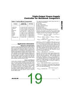
Table 3 lists two commercially available transformers
a nd pa rts for a c ustom tra nsforme r. The following
instructions show how to determine the transformer
parameters required for a custom design:
P
S
as possible, preferably in the low milliohms. Use the
largest gauge wire that will fit on the core. The coil is
effectively in series with the load at all times, so the
re s is tive los s e s in the p rima ry wind ing a lone a re
2
)
approximately (I
x R .
TOTAL
P
L , the primary inductance value
P
The minimum turns ratio, N , is 5V:(15V-5V). Use 1:2.2
I
, the peak primary current
MIN
LPEAK
2
to accommodate the tolerance of the +5V supply.
A
LI , the core’s energy rating
and R , the primary and secondary resistances
MAX782
greater ratio will reduce efficiency of the VPP regulators.
R
P
S
N, the primary-to-secondary turns ratio.
Minimize the diode capacitance and the interwinding
c a p a c ita nc e , s inc e the y c re a te los s e s throug h the
VDD shunt regulator. These are most significant when
the input voltage is high, the +5V load is heavy, and
there is no load on VDD.
The transformer primary is specified just as the +3.3V
inductor, using V
= +5.0V; but the secondary output
OUT
(VDD) power must be added in as if it were part of the
primary. VDD current (I ) usually includes the VPPA
DD
and VPPB output currents. The total +5V power, P
is the sum of these powers:
,
TOTAL
Ensure the transformer secondary is connected with the
right polarity: A VDD supply will be generated with either
polarity, but proper operation is possible only with the cor-
rect polarity. Test for correct connection by measuring the
VDD voltage when VDD is unloaded and the input voltage
P
= P5 + P
DD
TOTAL
where:
and:
P5 = V
x I
;
;
OUT
OUT
P
= VDD x I
DD
DD
(V ) is varied over its full range. Correct connection is
IN
V
OUT
= output voltage, 5V;
indicated if VDD is maintained between 13V and 20V.
I
= maximum +5V load current (A);
OUT
VDD = VDD output voltage, 15V;
= maximum VDD load current (A);
Current-Sense Resistors (R1, R2)
The sense resistors must carry the peak current in the
ind uc tor, whic h e xc e e d s the full DC loa d c urre nt.
The internal current limiting starts when the voltage
across the sense resistors exceeds 100mV nominally,
80mV minimum. Use the minimum value to ensure
adequate output current capability: For the +3.3V
I
DD
so:
P
= (5V x I ) + (15V x I )
OUT DD
TOTAL
and the equivalent +5V output current, I
, is:
TOTAL
I
= P
/ 5V
TOTAL
TOTAL
= [(5V x I ) + (15V x I )] / 5V.
OUT DD
The primary inductance, L , is given by:
P
V
OUT
x
(V
IN(MAX)
- V
)
supply, R1 = 80mV / (1.15 x I ); for the +5V supply,
OUT
OUT
L
P
= ———————————————
R2 = 80mV/(1.15 x I ), assuming that LIR = 0.3.
TOTAL
V
x f x I
x LIR
IN(MAX)
TOTAL
Since the sense resistance values (e.g. R1 = 25mΩ for
= 3A) are similar to a few centimeters of narrow
where:
V
OUT
= output voltage, 5V;
I
OUT
V
= maximum input voltage;
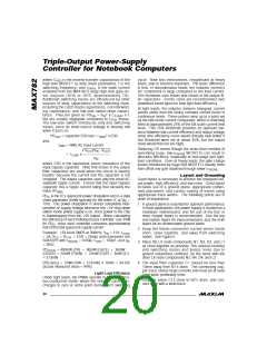
traces on a printed circuit board, trace resistance can
contribute significant errors. To prevent this, Kelvin
connect the CS_ and FB_ pins to the sense resistors;
i.e., use separate traces not carrying any of the induc-
tor or load current, as shown in Figure 5.
IN(MAX)
f = switching frequency, normally 300kHz;
= maximum equivalent load current (A);
I
TOTAL
LIR = ratio of primary peak-to-peak AC
current to average DC load current, typically 0.3.
The highest peak primary current (I ) equals the
total DC load current (I
AC primary current (I ). The peak-to-peak AC primary
current is typically chosen as 30% of the maximum DC
load current, so the peak primary current is 1.15 times
. A higher value of LIR allows smaller inductance,
but results in higher losses and higher ripple.
Run these traces parallel at minimum spacing from one
another. The wiring layout for these traces is critical for
s ta b le , low-rip p le outp uts (s e e the La yout a nd
Grounding section).
LPEAK
) plus half the peak-to-peak
TOTAL
LPP
MOS FET S w it c h e s (N1 -N4 )
The four N-channel power MOSFETs are usually iden-
tical and must be “logic-level” FETs; that is, they must
I
TOTAL
The peak current in the primary at full load is given by:
b e fully on (ha ve low r
) with only 4V g a te -
DS(ON)
V
OUT
x (V
) - V
)
source drive voltage. The MOSFET r
should
IN(MAX
OUT
DS(ON)
I
= I
TOTAL
+ —————————————.
2 x f x L x V
ideally be about twice the value of the sense resistor.
MOSFETs with even lower r have higher gate
LPEAK
P
IN(MAX)
DS(ON)
c a p a c ita nc e , whic h inc re a s e s s witc hing time a nd
transition losses.
2
Choose a core with an LI parameter greater than L
x
P
2
I
.
LPEAK
16 ______________________________________________________________________________________

 MAXIM [ MAXIM INTEGRATED PRODUCTS ]