2x4-Channel, Simultaneous-Sampling
12-Bit ADCs
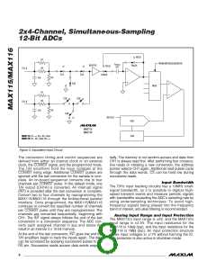
HOLD
R1
FROM MICROSEQUENCER
C
HOLD
7pF
BUFFER
TRACK
HOLD
R2
CH_A
S1A
S2A
TRACK
C
R3
IN
S3A
MUX
R1
R2
S1B
S2B
CH_B
C
R3
IN
S3B
REFOUT
DAC
SAR
MAX115
MAX116
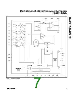
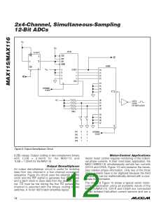
MAX115: R1 = R2 = R3 = 5k
MAX116: R1 = R2 = 5k R3 =
Figure 3. Equivalent Input Circuit
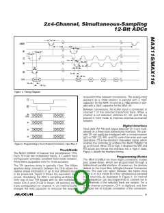
The conversion timing and control sequences are
derived from either an internal clock or an external
clock, the CONVST signal, and the programmed mode.
The T/H amplifiers hold the input voltages at the
CONVST rising edge. Additional CONVST pulses are
ignored until the last conversion for the sample is com-
plete. An on-board sequencer converts one to four
channels per CONVST pulse. In the default mode, one
T/H output (CH1A) is converted. An interrupt signal
(INT) is provided after the last conversion is complete.
Convert two to four channels by reprogramming the
MAX115/MAX116 through the bidirectional parallel
interface. Once programmed, the MAX115/MAX116
continues to convert the specified number of channels
per CONVST pulse until they are reprogrammed. The
channels are converted sequentially, beginning with
CH1. The INT signal always follows the end of the last
conversion in a conversion sequence. The ADC con-
verts each assigned channel in 2µs and stores the
result in an internal 4 x 12-bit memory.
tially. The memory is not random-access and data from
CH1 is always read first. After performing four consecu-
tive reads or initiating a new conversion, the address
pointer selects CH1 again. Additional read pulses cycle
through the data words. CS can be held low during
successive reads.
Input Bandwidth
The T/H’s input tracking circuitry has a 10MHz small-
signal bandwidth, so it is possible to digitize high-
speed transient events and measure periodic signals
with bandwidths exceeding the ADC’s sampling rate by
using undersampling techniques. To avoid high-
frequency signals being aliased into the frequency
band of interest, anti-alias filtering is recommended.
Analog Input Range and Input Protection
The MAX115’s input range is 5V, and the MAX116’s
input range is 2.5V. The input resistance for the
MAX115 is 10k (typ), and the input resistance for the
MAX116 is 1M (typ). An input protection structure
allows input voltages to 1ꢀV without harming the IC.
This protection is also active in shutdown mode.
At the end of the last conversion, INT goes low and the
T/H amplifiers begin to track the inputs again. The data
can be accessed by applying successive pulses to the
RD pin. Successive reads access data words sequen-
8
_______________________________________________________________________________________

 MAXIM [ MAXIM INTEGRATED PRODUCTS ]