2x4-Channel, Simultaneous-Sampling
12-Bit ADCs
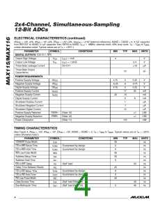
ELECTRICAL CHARACTERISTICS (continued)
(AV
= +5V 5ꢁ, AV = -5V 5ꢁ, DV
= +5V 5ꢁ, V
= +2.5V (external reference), AGND = DGND = 0, 4.ꢀµF capacitor
DD
SS
DD
REFIN
from REFOUT to AGND, 0.1µF capacitor from REFIN to AGND, f
= 16MHz, external clock, 50ꢁ duty cycle. T = T
to T
,
MAX
CLK
A
MIN
unless otherwise noted. Typical values are at T = +25°C.)
A
PARAMETER
SYMBOL
CONDITIONS
MIN
TYP
MAX
UNITS
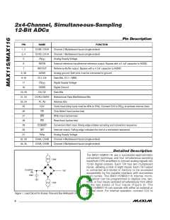
DIGITAL OUTPUTS (D0–D11, INT)
Output High Voltage
V
I
I
= 1mA
4
V
V
OH
OUT
Output Low Voltage
V
= -1.6mA
0.4
10
OL
OUT
Three-State Leakage Current
D0–D11
µA
Three-State Output
Capacitance
10
pF
POWER REQUIREMENTS
Positive Supply Voltage
Negative Supply Voltage
Digital Supply Voltage
AV
4.ꢀ5
-5.25
4.ꢀ5
5
-5
5
5.25
-4.ꢀ5
5.25
25
V
V
DD
AV
SS
DD
DV
V
Positive Supply Current
Negative Supply Current
Digital Supply Current
I
1ꢀ
-15
3
mA
mA
mA
µA
µA
µA
LSB
LSB
mW
AVDD
I
-20
AVSS
6
Shutdown Positive Current
Shutdown Negative Current
Shutdown Digital Current
1
-1
13
Positive Supply Rejection
Negative Supply Rejection
Power Dissipation
PSRR+
PSRR-
(Note 10)
(Note 10)
(Note 11)
1
1
1ꢀ5
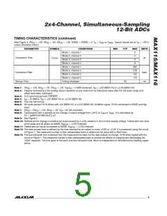
TIMING CHARACTERISTICS
(See Figure 4, AV
= +5V, AV = -5V, DV
= +5V, AGND = DGND = 0, T = T
A
to T , Typical values are at T = +25°C,
MAX A
DD
SS
DD
MIN
unless otherwise noted.)
PARAMETER
SYMBOL
CONDITIONS
MIN
30
0
TYP
MAX
UNITS
ns
t
CONVST Pulse Width
CS to WR Setup Time
CS to WR Hold Time
WR Low Pulse Width
Address Setup Time
Address Hold Time
RD to INT Delay
CW
t
Guaranteed by design
Guaranteed by design
ns
CWS
t
0
ns
CWH
t
30
30
0
ns
WR
t
AS
ns
t
ns
AH
t
ID
25pF load
55
ns
Delay Time Between Reads
CS to RD Setup Time
CS to RD Hold Time
RD Low Pulse Width
Data-Access Time
t
45
0
ns
RD
t
Guaranteed by design
Guaranteed by design
ns
CRS
CRH
t
0
ns
t
30
ns
RD
t
25pF load (Note 12)
25pF load (Note 13)
40
45
ns
DA
DH
Bus-Relinquish Time
t
5
ns
4
_______________________________________________________________________________________

 MAXIM [ MAXIM INTEGRATED PRODUCTS ]