2x4-Channel, Simultaneous-Sampling
12-Bit ADCs
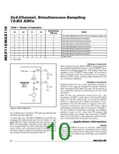
Table 1. Modes of Operation
CONVERSION
TIME (µs)
A3
A2
A1
A0
MODE
0
0
0
0
0
0
0
0
1
0
0
0
0
1
1
1
1
X
0
0
1
1
0
0
1
1
X
0
1
0
1
0
1
0
1
X
2
4
Input Mux A/Single-Channel Conversion (default at power-up)
Input Mux A/Two-Channel Conversion
Input Mux A/Three-Channel Conversion
Input Mux A/Four-Channel Conversion
Input Mux B/Single-Channel Conversion
Input Mux B/Two-Channel Conversion
Input Mux B/Three-Channel Conversion
Input Mux B/Four-Channel Conversion
Power-Down
6
8
2
4
6
8
—
X = Don’t care
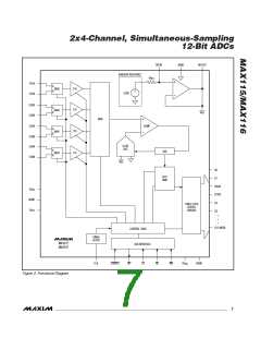
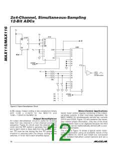
Starting a Conversion
After programming the MAX115/MAX116 as outlined in
the Programming Modes section, pulse CONVST low to
initiate a conversion sequence. The analog inputs are
sampled at the CONVST rising edge. Do not start a
new conversion while the conversion is in progress.
Monitor the INT output. A falling edge indicates the end
of a conversion sequence.
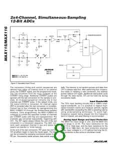
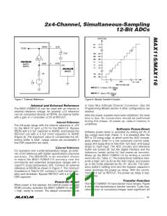
REFOUT
REFIN
7
(2.5V)
(2.5V)
TO DAC
4.7 F
A
V
= 1
6
Reading a Conversion
Digitized data from up to four channels is stored in
memory to be read out through the parallel interface.
After receiving an INT signal, the user can access up to
four conversion results by performing up to four read
operations.
MAX115
MAX116
0.1 F
10k
2.5V
With CS low, the conversion results from CH1_ are
accessed, and INT is reset high on the first RD falling
edge. On the RD rising edge, the internal address
pointer is advanced. If a single conversion is pro-
grammed, only one RD pulse is required. For multi-
channel conversions, up to four RD falling edges
sequentially access the data for channels 1 through 4.
For any number of channels converted, the address
pointer is reset to CH1_ after four RD pulses. The
address pointer also resets after receiving a CNVST
pulse. Do not perform a read operation during conver-
sion; it will corrupt the conversion’s accuracy.
Figure 6. Internal Reference
For multichannel conversions, INT goes low after the last
channel has been digitized.
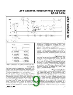
To input data into the MAX115/MAX116, pull CS low,
program the bidirectional pins A0–A3 (Table 1), and
pulse WR low. Data is latched into the devices on the
WR or CS rising edge. The ADC is now ready to convert.
Once programmed, the ADC continues operating in the
same mode until reprogrammed or until power is
removed. Figure 5 shows an example of programming a
four-channel conversion using Input Mux A.
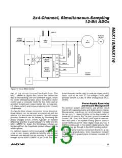
__________Applications Information
Clock
The MAX115/MAX116 have an internal 10MHz (typ)
clock, which is activated by connecting CLK to DV
DD
(internal clock startup time is 165µs typ). The CLK input
also accepts an external clock with duty cycle between
30ꢁ and ꢀ0ꢁ.
10 ______________________________________________________________________________________

 MAXIM [ MAXIM INTEGRATED PRODUCTS ]