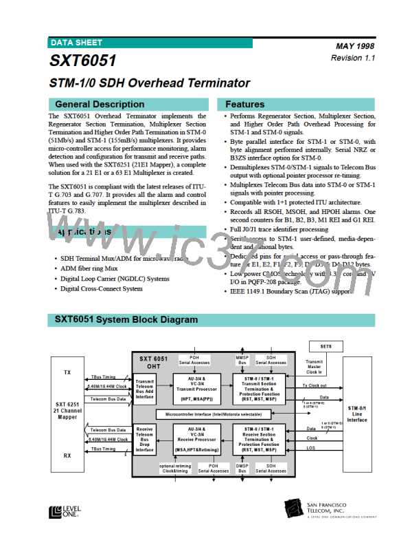
SXT6051 STM-1/0 SDH Overhead Terminator
Table 2: Signal Description (Sheet 11 of 11)
Pin #
Name
Type
Description
JTAG test ports
110
109
JTCK
JTMS
I
JTAG Clock. Clock for all boundary scan circuitry.
Test Mode Select. Determine state of TAP controller.
TTLin
I
TTLin
(48K pull up)
108
JTRS
I
Reset. Active Low.
TTLin
(35K pull
down)
107
106
JTDI
I
Data Input. Input signal used to shift in instructions and data.
TTLin (48K
pull up)
JTDO
O
Data Output. Output signal used to shift out instructions and
2mA
data.
Scan input pins
158
SCANTEST
I
Scan test mode. Active Low.
Scan Enable. Active Low.
TTLin (48 K
pull up)
111
SCANEN
I
TTLin (48K
pull up)
Table 3: Power, Ground, and No Connects
Pin # Name
14, 38, 52, 65, 95, 105, 134, 156, 178, 208 VCC_5
Type
Power Supply
5V Supply.
1, 27, 47, 53, 83, 104, 123, 146, 157, 199
36, 84, 139, 175, 193
GND_5
VCC_3
GND_3
NC
GND 5 Volts. Ground pins for 5 Volt supply.
3 V supply.
37, 85, 138, 174, 190
GND 3 Volts. Ground pins for 3 Volt supply.
Not Connected. Unused. Leave unconnected.
162, 164, 189, 207
18

 LevelOne [ LEVEL ONE ]