SXT6051 STM-1/0 SDH Overhead Terminator
The output of this block is then sent to the Receive Telecom
Bus DTBDATA<7:0> with the DTBCLK clock and refer-
ence timing DTBJ0J1EN and DTBPAYEN.
• Terminal Mode Protection Slave
• Add And Drop Mode No Protection
• Add And Drop Mode Protection Main
• Add And Drop Mode Protection Slave
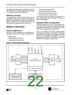
Reference Clocks
Note that the following are examples of configurations. For
more details, please refer to AN9801: SXT6051 &
SXT6251 SDH Chipset.
The transmit and the receive side of the SXT6051 operate
independently. In the STM-0 case, the input and output can
either be serial or parallel. In the STM-1 case, the input and
output are parallel only. The following table shows the
clock connections required for STM-1 and STM-0:
Repeater Mode Configuration
All MSOH, HPOH and VC data is passed through inter-
nally and no off chip connection is required between the
transmit and the receive sides. The transmit source of the
RSOH bytes is configurable (see register 60H).
Modes of Operation
Chip Configuration
The SXT6051 can be programmed in seven different con-
figurations in STM-0 or STM-1 mode (see register 50H.)
Figure 3 is an example of an STM-0 repeater using the
serial interface. The timing is recovered by the high-speed
line interface unit and passed to the transmit side via the
SXT6051. In the event of a receiver failure (i.e., a LOS of
Signal Alarm), the SXT6051 will switch to a Blue signal
reference if so configured (see register 40H).
• Repeater mode
• Terminal Mode No Protection
• Terminal Mode Protection Main
Figure 3: STM-0 Repeater Application
D1
B1
B2
E1
F1
to
D3
Error Error
J0
STM-0
B3Zs
Encoded
Serial clock
Serial Data
Los Alarm
STM-0
B3Zs
encoded
Serial clock
Serial Data
SSI 7200
Line
Interface
SSI 7200
Line
Interface
SXT 6051
Regenerator Configuration
51.84 Mbit/s
51.84Mbit/s
Pass Through Programmable
Microprocessor
for Configuration and
Network Management
Interface
51.84 MHz ±20 ppm
Local Reference for Blue
Signal Generation
22

 LevelOne [ LEVEL ONE ]