SXT6051 STM-1/0 SDH Overhead Terminator
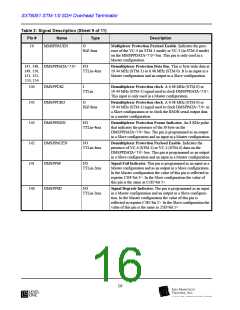
Table 2: Signal Description (Sheet 7 of 11)
Pin #
Name
Type
Description
126
RMD
O
Receive MSOH D4-D12 Data. A 576 Kb/s data output for
HiZ-2ma
MSOH D4-D12 data. Data is clocked out by RMDC.
125
RMDC
O
Receive MSOH D4-D12 Data Clock. A 576 KHz reference
HiZ-2ma
signal used to clock out RMD data.
Telecom Bus Interface
66, 67, 68, MTBDATA<7:0>
69, 70, 71,
72, 73
I
Multiplexer Telecom Bus Data. A byte-wide data input at
19.44 Mbit/s for STM-1 or 6.48 Mbit/s for STM-0. Non-pay-
load byte timeslots (i.e., RSOH, AU pointer, MSOH and
HPOH timeslots) can either have a 0 or 1 inserted.
TTLin
74
75
MTBPAR
MTBCKI
I
Multiplexer Telecom Bus Parity. This is a parity check calcu-
lated on each MTBDATA<7:0> byte. It is an odd parity.
TTLin
I
Multiplexer Telecom Bus Clock Input. A 6.48MHz (STM-0)
or 19.44 MHz (STM-1) input signal used to clock MTB-
DATA<7:0>. It is used when the SXT6051 is configured as an
ADM. In other configurations the pin should be tied to ground.
TTLin
76
77
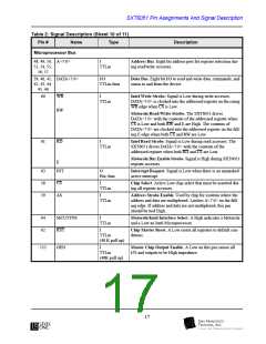
MTBCKO
O
Multiplexer Telecom Bus Clock Output. A 6.48MHz (STM-
0) or 19.44 MHz (STM-1) output signal. It is used when the
SXT6051 is used in a Terminal configuration.
HiZ-8ma
MTBJ0J1EN
I/O
TTLin-4ma
Multiplexer Telecom Bus Frame Indicator. It indicates the
presence of J0 and J1 bytes on the transmit bus. In an ADM
configuration the pin is set up as an input while in the terminal
mode it is set up as an output.
78
79
80
81
MTBTUGEN1
MTBTUGEN2
MTBTUGEN3
MTBPAYEN
O
Multiplexer Telecom Bus Payload Enable 1. Indicates the
presence of TUG3#1 in the case of STM-1. In the case of STM-
0 this pin is internally pulled High. In ADM it is not used.
HiZ-4ma
O
Multiplexer Telecom Bus Payload Enable 2. Indicates the
presence of TUG3#2 in the case of STM-1. In the case of STM-
0 this pin is internally pulled High. In ADM it is not used.
HiZ-4ma
O
Multiplexer Telecom Bus Payload Enable 3. Indicates the
presence of TUG3#3 in the case of STM-1. In the case of STM-
0 this pin is internally pulled High. In ADM it is not used.
HiZ-4ma
I/O
TTLin-4ma
Multiplexer Telecom Bus Payload Enable Signal. Indicates
the presence of VC-4 in the STM-1 mode or VC-3 in the STM-
0 mode. This signal is used as an output when the SXT6051 is
configured in a Terminal mode and an input in ADM mode.
82
MTBH4EN
TTLin-4ma
Multiplexer Telecom Bus H4 Multi-Frame Indicator. As an
output, it is a 2 KHz signal that indicates the location of the 00
value of H4. The signal goes High after H4 equals “00 “and
Low after H4 equals” 01”. Used as an output when the
SXT6051 is configured in a Terminal Mode. As an input (in
ADM) it is sampled at the J1 byte location.
14

 LevelOne [ LEVEL ONE ]