LTC1622
U
W U U
APPLICATIONS INFORMATION
The basic LTC1622 application circuit is shown in Figure
V
OUT. The inductor’s peak-to-peak ripple current is given
1. External component selection is driven by the load
by:
requirementandbeginswiththeselectionofLandRSENSE
Next, the Power MOSFET and the output diode D1 are
selected followed by CIN and COUT
.
V − V
V
+ V
IN
OUT OUT D
I
=
RIPPLE
V + V
f L
( )
.
IN
D
wherefistheoperatingfrequency.Acceptinglargervalues
of IRIPPLE allows the use of low inductances, but results in
higher output voltage ripple and greater core losses. A
reasonable starting point for setting ripple current is
RSENSE Selection for Output Current
RSENSE is chosen based on the required output current.
Withthecurrentcomparatormonitoringthevoltagedevel-
oped across RSENSE, the threshold of the comparator
determines the inductor’s peak current. The output cur-
rent the LTC1622 can provide is given by:
I
RIPPLE =0.4(IOUT(MAX)).Remember,themaximumIRIPPLE
occurs at the maximum input voltage.
With Burst Mode operation selected on the LTC1622, the
ripple current is normally set such that the inductor
current is continuous during the burst periods. Therefore,
the peak-to-peak ripple current should not exceed:
0.08
I
RIPPLE
I
=
−
OUT
R
2
SENSE
where IRIPPLE is the inductor peak-to-peak ripple current
(see Inductor Value Calculation section).
0.036
I
≤
RIPPLE
R
SENSE
A reasonable starting point for setting ripple current is
IRIPPLE = (0.4)(IOUT). Rearranging the above equation, it
becomes:
This implies a minimum inductance of:
V − V + V
V
IN
OUT
OUT
D
L
=
1
MIN
R
=
for Duty Cycle < 40%
V + V
SENSE
0.036
IN
D
15 I
f
OUT
( )(
)
R
SENSE
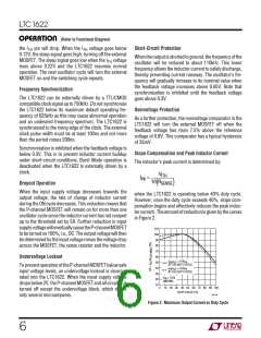
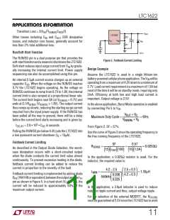
However,foroperationthatisabove40%dutycycle,slope
compensation has to be taken into consideration to select
the appropriate value to provide the required amount of
current. Using Figure 2, the value of RSENSE is:
(Use VIN(MAX) = VIN)
A smaller value than LMIN could be used in the circuit;
however, the inductor current will not be continuous
during burst periods.
SF
R
=
SENSE
Inductor Core Selection
15
I
100
)(
( )(
)
OUT
Once the value for L is known, the type of inductor must be
selected. High efficiency converters generally cannot
affordthecorelossfoundinlowcostpowderedironcores,
forcing the use of more expensive ferrite, molypermalloy
or Kool Mu® cores. Actual core loss is independent of core
size for a fixed inductor value, but it is very dependent on
inductance selected. As inductance increases, core losses
go down. Unfortunately, increased inductance requires
more turns of wire and therefore copper losses will
increase. Ferritedesignshaveverylowcorelossesandare
Inductor Value Calculation
The operating frequency and inductor selection are inter-
related in that higher operating frequencies permit the use
of a smaller inductor for the same amount of inductor
ripplecurrent. However, thisisattheexpenseofefficiency
due to an increase in MOSFET gate charge losses.
The inductance value also has a direct effect on ripple
current. The ripple current, IRIPPLE, decreases with higher
inductance or frequency and increases with higher VIN or
Kool Mu is a registered trademark of Magnetics, Inc.
7

 Linear [ Linear ]