LTC1622
The ● denotes specifications which apply over the full operating
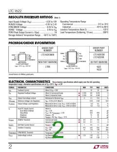
ELECTRICAL CHARACTERISTICS
temperature range, otherwise specifications are at TA = 25°C. VIN = 4.2V
SYMBOL
PARAMETER
CONDITIONS
MIN
TYP
MAX
UNITS
PDRV t
PDRV t
Gate Drive Rise Time
Gate Drive Fall Time
C
C
= 3000pF
= 3000pF
80
100
140
140
ns
ns
r
f
LOAD
LOAD
∆V
SENSE(MAX)
Maximum Current Sense Voltage
●
80
110
140
mV
Note 1: Absolute Maximum Ratings are those values beyond which the life
of a device may be impaired.
Note 3: The LTC1622 is tested in a feedback loop that servos V to the
FB
feedback point for the error amplifier (V = 0.8V).
ITH
Note 2: T is calculated from the ambient temperature T and power
Note 4: Dynamic supply current is higher due to the gate charge being
delivered at the switching frequency.
J
A
dissipation P according to the following formula:
D
LTC1622CS8; T = T + (P • 150°C/W),
J
A
D
LTC1622CMS8; T = T + (P • 250°C/W)
J
A
D
W
U
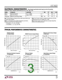
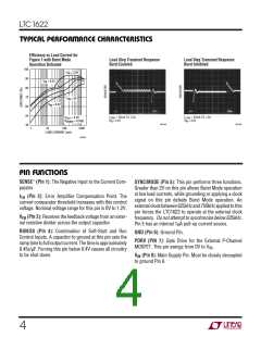
TYPICAL PERFORMANCE CHARACTERISTICS
Shutdown Current
vs Supply Voltage
Maximum Current Sense Voltage
vs Duty Cycle
RUN/SS Current vs Supply Voltage
45
40
35
30
25
20
15
10
5
3.50
3.00
2.50
2.00
1.50
1.00
110
100
90
V
IN
= 4.2V
UNSYNC
80
70
60
50
40
0
30
6
7
2
3
4
5
6
7
8
9
10
60 70
DUTY CYCLE (%)
2
3
4
5
8
9
10
20 30
100
40 50
80 90
SUPPLY VOLTAGE (V)
SUPPLY VOLTAGE (V)
1622 G01
1622 G02
1622 G03
Normalized Oscillator Frequency
vs Temperature
Reference Voltage
vs Temperature
Undervoltage Lockout Voltage
vs Temperature
10.0
7.5
0.810
0.805
0.800
0.795
0.790
0.785
0.780
0.775
2.10
2.05
2.00
1.95
1.90
1.85
1.80
1.75
V
IN
= 4.2V
V
= 4.2V
IN
5.0
2.5
0
–2.5
–5.0
–7.5
–10.0
25 45 65
5
TEMPERATURE (°C)
–55 –35 –15
25 45 65
5
TEMPERATURE (°C)
85 105 125
25 45 65
5
TEMPERATURE (°C)
–55 –35 –15
85 105 125
–55 –35 –15
85 105 125
1622 G04
1622 G05
1622 G06
3

 Linear [ Linear ]