LTC3630
APPLICATIONS INFORMATION
The current that flows through the R3-R4 divider will
directly add to the shutdown, sleep, and active current
of the LTC3630, and care should be taken to minimize
the impact of this current on the overall efficiency of the
The minimum soft-start time is limited to the internal soft-
start timer of 0.8ms. When the LTC3630 detects a fault
condition(inputsupplyundervoltageorovertemperature)
or when the RUN pin falls below 1.1V, the SS pin is quickly
pulled to ground and the internal soft-start timer is reset.
This ensures an orderly restart when using an external
soft-start capacitor.
application circuit. To keep the variation of the rising V
IN
UVLO threshold to less than 5% due to the internal pull-
up circuitry, the following equations should be used to
calculate R3 and R4:
Note that the soft-start capacitor may not be the limiting
factor in the output voltage ramp. The maximum output
current, which is equal to half the peak current, must
charge the output capacitor from 0V to its regulated value.
For small peak currents or large output capacitors, this
ramptimecanbesignificant.Therefore,theoutputvoltage
RisingV UVLOThreshold
IN
R3 ≤
40ꢀA
R3 •1.21V
R4 =
RisingV UVLOThreshold– 1.21V+R3 • 4ꢀA
IN
ramp time from 0V to the regulated V
to a minimum of:
value is limited
OUT
The falling UVLO threshold will be about 10% lower than
therisingV UVLOthresholdduetothe110mVhysteresis
IN
2 •COUT
IPEAK
of the RUN comparator.
Ramp Time ≥
VOUT
For applications that do not require a precise UVLO, the
RUNpincanbeleftfloating.Inthisconfiguration,theUVLO
C
ISET
Selection
threshold is limited to the internal V UVLO thresholds as
IN
Once the peak current resistor, R , and inductor are se-
shown in the Electrical Characteristics table.
ISET
lectedtomeettheloadcurrentandfrequencyrequirements,
Be aware that the RUN pin cannot be allowed to exceed
its absolute maximum rating of 6V. To keep the voltage
on the RUN pin from exceeding 6V, the following relation
should be satisfied:
an optional capacitor, C , can be added in parallel with
ISET
R
. This will boost efficiency at mid-loads and reduce
ISET
theoutputvoltagerippledependencyonloadcurrentatthe
expenseofslightlydegradedloadsteptransientresponse.
V
< 4.5 • Rising V UVLO Threshold
IN
IN(MAX)
The peak inductor current is controlled by the voltage on
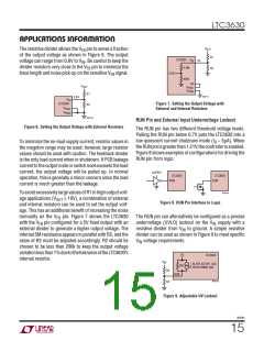
To support a V
greater than 4.5x the external UVLO
the I
pin. Current out of the I
pin is 5ꢀA while the
IN(MAX)
SET
SET
threshold, an external 4.7V Zener diode should be used
in parallel with R4. See Figure 11.
LTC3630 is switching and is reduced to 1ꢀA during sleep
mode. The I current will return to 5ꢀA on the first cycle
SET
after sleep mode. Placing a parallel RC from the I pin to
SET
Soft-Start
ground filters the I voltage as the LTC3630 enters and
SET
exits sleep mode which in turn will affect the output volt-
Soft-start is implemented by ramping the effective refer-
ence voltage from 0V to 0.8V. To increase the duration of
soft-start, place a capacitor from the SS pin to ground.
An internal 5ꢀA pull-up current will charge this capacitor.
The value of the soft-start capacitor can be calculated by
the following equation:
ageripple, efficiencyandloadsteptransientperformance.
In general, when R
is greater than 120k a C
ca-
ISET
ISET
pacitor in the 100pF to 200pF range will improve most
performance parameters. When R is less than 100k,
ISET
the capacitance on the I pin should be minimized.
SET
5ꢀA
0.35V
CSS = Soft-Start Time •
3630fb
16

 Linear Systems [ Linear Systems ]