LTC3630
APPLICATIONS INFORMATION
1000
100
10
600
V
SET
= 3.3V
OUT
L = 4.2ꢀH
I
OPEN
500
400
300
200
100
0
L = 10ꢀH
L = 22ꢀH
L = 47ꢀH
L = 100ꢀH
50
20
30
40
0
10
60
100
1000
V
INPUT VOLTAGE (V)
PEAK INDUCTOR CURRENT (mA)
IN
3630 F04
3630 F03
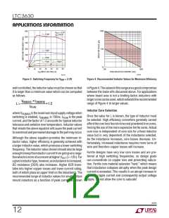
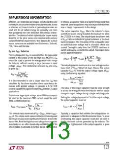
Figure 4. Recommended Inductor Values for Maximum Efficiency
Figure 3. Switching Frequency for VOUT = 3.3V
well-controlled, the inductor value must be chosen so that
it is larger than a minimum value which can be computed
as follows:
inFigure4.Thevaluesinthisrangeareagoodcompromise
between the trade-offs discussed above. For applications
where board area is not a limiting factor, inductors with
largercorescanbeused,whichextendstherecommended
range of Figure 4 to larger values.
VIN(MAX) • tON(MIN)
L >
•1.2
IPEAK
Inductor Core Selection
whereV
isthemaximuminputsupplyvoltagewhen
IN(MAX)
switching is enabled, t
Once the value for L is known, the type of inductor must
be selected. High efficiency converters generally cannot
affordthecorelossfoundinlowcostpowderedironcores,
forcing the use of the more expensive ferrite cores. Actual
core loss is independent of core size for a fixed inductor
value but is very dependent of the inductance selected.
As the inductance increases, core losses decrease. Un-
fortunately, increased inductance requires more turns of
wire and therefore copper losses will increase.
is 150ns, I
is the peak
ON(MIN)
PEAK
current, and the factor of 1.2 accounts for typical inductor
tolerance and variation over temperature. Inductor values
that violate the above equation will cause the peak current
toovershootandpermanentdamagetothepartmayoccur.
Although the above equation provides the minimum in-
ductor value, higher efficiency is generally achieved with
a larger inductor value, which produces a lower switching
frequency. The inductor value chosen should also be large
enoughtokeeptheinductorcurrentfromgoingverynega-
Ferrite designs have very low core losses and are pre-
ferred at high switching frequencies, so design goals
can concentrate on copper loss and preventing satura-
tion. Ferrite core material saturates “hard,” which means
that inductance collapses abruptly when the peak design
current is exceeded. This results in an abrupt increase in
inductor ripple current and consequently output voltage
ripple. Do not allow the core to saturate!
tivewhichismoreofaconcernathigherV
(>~12V).For
OUT
agiveninductortype,however,asinductanceisincreased,
DC resistance (DCR) also increases. Higher DCR trans-
lates into higher copper losses and lower current rating,
both of which place an upper limit on the inductance. The
recommended range of inductor values for small surface
mount inductors as a function of peak current is shown
3630fb
12

 Linear Systems [ Linear Systems ]