LTC3630
APPLICATIONS INFORMATION
V
OUT
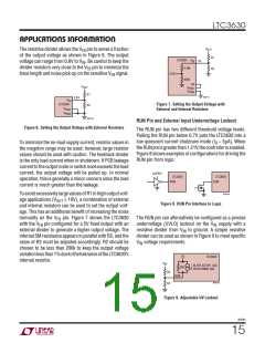
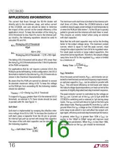
The resistive divider allows the V pin to sense a fraction
FB
of the output voltage as shown in Figure 6. The output
R1
LTC3630
4.2M
V
5V
FB
voltage can range from 0.8V to V . Be careful to keep the
IN
divider resistors very close to the V pin to minimize the
R2
FB
0.8V
trace length and noise pick-up on the sensitive V signal.
FB
800k
SS
PRG1
PRG2
V
OUT
V
V
R1
3630 F07
0.8V
V
FB
LTC3630
V
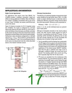
Figure 7. Setting the Output Voltage with
External and Internal Resistors
R2
PRG1
V
PRG2
3630 F06
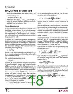
RUN Pin and External Input Undervoltage Lockout
Figure 6. Setting the Output Voltage with External Resistors
The RUN pin has two different threshold voltage levels.
Pulling the RUN pin below 0.7V puts the LTC3630 into a
low quiescent current shutdown mode (I ~ 5ꢀA). When
To minimize the no-load supply current, resistor values in
the megohm range may be used; however, large resistor
values should be used with caution. The feedback divider
is the only load current when in shutdown. If PCB leakage
currenttotheoutputnodeorswitchnodeexceedstheload
current, the output voltage will be pulled up. In normal
operation, this is generally a minor concern since the load
current is much greater than the leakage.
Q
theRUNpinisgreaterthan1.21V,thecontrollerisenabled.
Figure 8 shows examples of configurations for driving the
RUN pin from logic.
SUPPLY
LTC3630
RUN
LTC3630
RUN
3630 F08
To avoid excessively large values of R1 in high output volt-
age applications (V
≥ 10V), a combination of external
OUT
Figure 8. RUN Pin Interface to Logic
and internal resistors can be used to set the output volt-
age. This has an additional benefit of increasing the noise
immunity on the V pin. Figure 7 shows the LTC3630
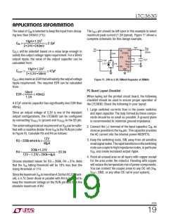
The RUN pin can alternatively be configured as a precise
FB
with the V pin configured for a 5V fixed output with an
undervoltage (UVLO) lockout on the V supply with a
FB
IN
external divider to generate a higher output voltage. The
internal 5M resistance appears in parallel with R2, and the
value of R2 must be adjusted accordingly. R2 should be
chosen to be less than 200k to keep the output voltage
variationlessthan1%duetothetoleranceoftheLTC3630’s
internal resistor.
resistive divider from V to ground. A simple resistive
IN
divider can be used as shown in Figure 9 to meet specific
V voltage requirements.
IN
5V
LTC3630
V
IN
SLEEP, ACTIVE: 2ꢀA
SHUTDOWN: 0ꢀA
2M
RUN
R3
R4
3630 F09
Figure 9. Adjustable UV Lockout
3630fb
15

 Linear Systems [ Linear Systems ]