LTC3630
APPLICATIONS INFORMATION
by I
= I
/2. Multiple capacitors placed in parallel
RMS
PEAK
L
IN
-5$ꢅꢆꢅꢁ
V
maybeneededtomeettheESRandRMScurrenthandling
requirements.
IN
LIN
CIN
R"
3630 F05
$
IN
Dry tantalum, special polymer, aluminum electrolytic,
and ceramic capacitors are all available in surface mount
packages. Special polymer capacitors offer very low ESR
but have lower capacitance density than other types.
Tantalum capacitors have the highest capacitance density
but it is important only to use types that have been surge
tested for use in switching power supplies. Aluminum
electrolytic capacitors have significantly higher ESR but
can be used in cost-sensitive applications provided that
consideration is given to ripple current ratings and long-
termreliability.CeramiccapacitorshaveexcellentlowESR
characteristics but can have high voltage coefficient and
audible piezoelectric effects. The high quality factor (Q)
of ceramic capacitors in series with trace inductance can
also lead to significant input voltage ringing.
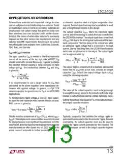
ꢈꢄtꢄ$
IN
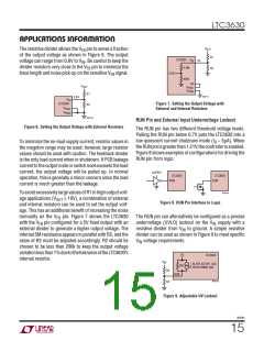
Figure 5. Series RC to Reduce VIN Ringing
Ceramic capacitors are also piezoelectric sensitive. The
LTC3630’s burst frequency depends on the load current,
and in some applications at light load the LTC3630 can
excite the ceramic capacitor at audio frequencies, gen-
erating audible noise. If the noise is unacceptable, use
a high performance tantalum or electrolytic capacitor at
the output.
Output Voltage Programming
The LTC3630 has three fixed output voltage modes that
Ceramic Capacitors and Audible Noise
can be selected with the V
and V
pins and an
PRG1
PRG2
Higher value, lower cost ceramic capacitors are now be-
coming available in smaller case sizes. Their high ripple
current, high voltage rating, and low ESR make them ideal
for switching regulator applications. However, care must
be taken when these capacitors are used at the input and
output. When a ceramic capacitor is used at the input and
thepowerissuppliedbyawalladapterthroughlongwires,
a load step at the output can induce ringing at the input,
adjustable mode. The fixed output modes use an internal
feedback divider which enables higher efficiency, higher
noise immunity, and lower output voltage ripple for 5V,
3.3V and 1.8V applications. To select the fixed 5V output
voltage, connect V
to SS and V
to GND. For 3.3V,
PRG1
to GND and V
PRG2
connect V
to SS. For 1.8V, connect
to SS. For any of the fixed output
PRG1
and V
PRG2
both V
PRG1
PRG2
voltage options, directly connect the V pin to V
.
FB
OUT
V . At best, this ringing can couple to the output and be
IN
For the adjustable output mode (V
= 0V, V
= 0V),
PRG1
PRG2
mistaken as loop instability. At worst, a sudden inrush
the output voltage is set by an external resistive divider
according to the following equation:
of current through the long wires can potentially cause
a voltage spike at V large enough to damage the part.
IN
⎛
⎝
⎞
⎟
⎠
R1
R2
For application with inductive source impedance, such as
alongwire,anelectrolyticcapacitororaceramiccapacitor
VOUT = 0.8V • 1+
⎜
with a series resistor may be required in parallel with C
IN
to dampen the ringing of the input supply. Figure 5 shows
this circuit and the typical values required to dampen the
ringing.
3630fb
14

 Linear Systems [ Linear Systems ]