LTC3630
APPLICATIONS INFORMATION
ThebasicLTC3630applicationcircuitisshownonthefront
page of the data sheet. External component selection is
determinedbythemaximumloadcurrentrequirementand
beginswiththeselectionofthepeakcurrentprogramming
between efficiency and light load output voltage ripple, as
described in the C
Selection section of the Applica-
ISET
tions Information. For maximum efficiency, minimize the
capacitance on the I pin and place the R resistor
SET
ISET
as close to the pin as possible.
resistor,R .TheinductorvalueLcanthenbedetermined,
ISET
followed by capacitors C and C
.
IN
OUT
Thetypicalpeakcurrentisinternallylimitedtobewithinthe
range of 120mA to 1.2A. Shorting the I pin to ground
SET
Peak Current Resistor Selection
programs the current limit to 120mA, and leaving it float
sets the current limit to the maximum value of 1.2A. When
selecting this resistor value, be aware that the maximum
average output current for this architecture is limited to
halfofthepeakcurrent.Therefore,besuretoselectavalue
that sets the peak current with enough margin to provide
adequate load current under all conditions. Selecting the
peak current to be 2.2 times greater than the maximum
load current is a good starting point for most applications.
The peak current comparator has a guaranteed maximum
current limit of 1A (1.2A typical), which guarantees a
maximum average current of 500mA. For applications
that demand less current, the peak current threshold can
be reduced to as little as 100mA (120mA typical). This
lower peak current allows the use of lower value, smaller
components (input capacitor, output capacitor, and induc-
tor), resulting in lower input supply ripple and a smaller
overall DC/DC converter.
Inductor Selection
The threshold can be easily programmed using a resis-
The inductor, input voltage, output voltage, and peak cur-
rent determine the switching frequency during a burst
cycle of the LTC3630. For a given input voltage, output
voltage, and peak current, the inductor value sets the
switching frequency during a burst cycle when the output
is in regulation. Generally, switching between 50kHz and
250kHz yields high efficiency, and 200kHz is a good first
choice for many applications. The inductor value can be
determined by the following equation:
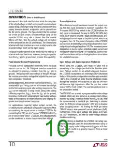
tor (R ) between the I pin and ground. The voltage
ISET
SET
pin by R
generated on the I
and the internal 5ꢀA
SET
ISET
current source sets the peak current. The voltage on the
I
pin is internally limited within the range of 0.1V to
SET
1.0V. The value of resistor for a particular peak current can
be selected by using Figure 2 or the following equation:
6
R
= I
• 0.2 • 10
ISET
PEAK
where 100mA < I
< 1A.
PEAK
⎛
⎜
⎝
⎞
⎟
⎠
⎛
⎞
VOUT
f •I
VOUT
V
IN
The internal 5μA current source is reduced to 1μA in sleep
mode to maximize efficiency and to facilitate a trade-off
L =
• 1–
⎜
⎟
⎠
⎝
PEAK
220
200
180
160
140
120
100
80
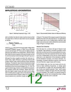
The variation in switching frequency during a burst cycle
withinputvoltageandinductanceisshowninFigure3. For
lower values of I
, multiply the frequency in Figure 3
PEAK
by 1.2A/I
.
PEAK
An additional constraint on the inductor value is the
LTC3630’s150nsminimumon-timeofthehighsideswitch.
Therefore, in order to keep the current in the inductor
60
40
20
0
50
150 200 250 300 350 400 450 500
100
MAXIMUM LOAD CURRENT (mA)
3630 F02
Figure 2. RISET Selection
3630fb
11

 Linear Systems [ Linear Systems ]