ISL6366
frequency that allows the regulator to meet the transient-response
0.3
0.2
0.1
0
I
I
= 0
I
I
= 0.5 I
O
L,PP
L,PP
and output-voltage ripple requirements. To minimize the effect of
cross coupling between regulators, select operating frequencies of
VR0 and VR1 at least 50kHz apart.
= 0.25 I
= 0.75 I
O
L,PP
O
L,PP
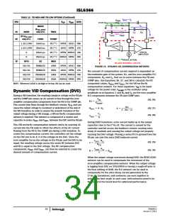
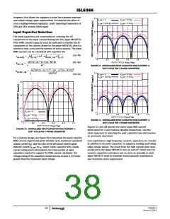
Input Capacitor Selection
The input capacitors are responsible for sourcing the AC
component of the input current flowing into the upper MOSFETs.
Their RMS current capacity must be sufficient to handle the AC
component of the current drawn by the upper MOSFETs which is
related to duty cycle and the number of active phases. The input
RMS current can be calculated with Equation 49.
(EQ. 49)
(EQ. 50)
3
2
2
2
2
I
=
K
• Io + K
• I
IN, RMS
IN, CM
RAMP, CM
Lo, PP
0
0.2
0.4
0.6
/V )
OUT IN
0.8
1.0
(N • D – m + 1) • (m – N • D)
DUTY CYCLE (V
K
=
--------------------------------------------------------------------------
IN, CM
2
N
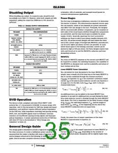
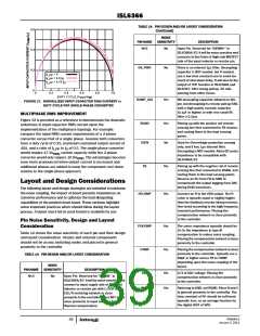
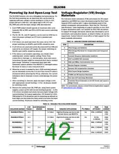
FIGURE 30. NORMALIZED INPUT-CAPACITOR RMS CURRENT vs
DUTY CYCLE FOR 3-PHASE CONVERTER
2
3
2
m (N • D – m + 1) + (m – 1) (m – N • D)
K
=
------------------------------------------------------------------------------------------------------------------
RAMP, CM
2
2
0.3
12N D
(EQ. 51)
I
I
= 0
= 0.25 I
I
I
= 0.5 I
O
L,PP
L,PP
L,PP
L,PP
= 0.75 I
O
O
0.3
0.2
0.1
0
0.2
0.1
I
I
I
= 0
L,PP
L,PP
L,PP
0
0.2
0.4
DUTY CYCLE (V
0.6
0.8
1.0
= 0.5 I
O
/V
)
OUT IN
= 0.75 I
0.2
O
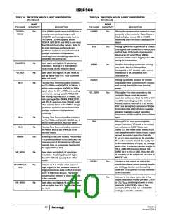
FIGURE 31. NORMALIZED INPUT-CAPACITOR RMS CURRENT vs
DUTY CYCLE FOR 4-PHASE CONVERTER
0
0
0.4
0.6
0.8
1.0
DUTY CYCLE (V
/V
)
OUT IN
Figures 27 and 28 provide the same input RMS current
information for 3 and 4-phase designs respectively. Use the
same approach to selecting the bulk capacitor type and number
as previously described.
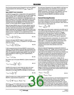
FIGURE 29. NORMALIZED INPUT-CAPACITOR RMS CURRENT vs
DUTY CYCLE FOR 2-PHASE CONVERTER
For a 2-phase design, use Figure 29 to determine the input capacitor
RMS current requirement given the duty cycle, maximum sustained
output current (I ), and the ratio of the per-phase peak-to-peak
Low capacitance, high-frequency ceramic capacitors are needed
in addition to the bulk capacitors to suppress leading and falling
edge voltage spikes. The result from the high current slew rates
produced by the upper MOSFETs turn on and off. Select low ESL
ceramic capacitors and place one as close as possible to each
upper MOSFET drain to minimize board parasitic impedances
and maximize noise suppression.
O
inductor current (I
) to I . Select a bulk capacitor with a ripple
L,PP
O
current rating which will minimize the total number of input
capacitors required to support the RMS current calculated. The
voltage rating of the capacitors should also be at least 1.25 times
greater than the maximum input voltage.
FN6964.0
January 3, 2011
38

 INTERSIL [ Intersil ]