ISL6366
TABLE 14. PIN DESIGN AND/OR LAYOUT CONSIDERATION
(Continued)
TABLE 14. PIN DESIGN AND/OR LAYOUT CONSIDERATION
(Continued)
NOISE
NOISE
PIN NAME SENSITIVITY
DESCRIPTION
PIN NAME
ISEN[6:1]-
SENSITIVITY
DESCRIPTION
PWMS
No
Avoid the routing across or under other
phase’s power trains and DCR sensing
network. Don’t make them across or under
external components of the controller. At
least 30mils away from any other traces.
Yes
Connect to the phase node side of the
respective channel’s output inductor or
resistor pin with L/DCR or ESL/R
SEN
matching network in close proximity to the
ISEN± pins of VR0. Differentially routing
back to the controller by paring with
respective ISEN+; at least 20 mils spacing
between pairs and away from other traces.
Each pair should not across the other
channel’s switching nodes [Phase, UGATE,
LGATE] and power planes even though they
are not in the same layer
ADDR_XX;
NPSI_XX;
BT_XX;
No
Register setting is locked prior to soft-start.
Since the external resistor-divider ratio
compares with the internal resistor ratio of
the VCC, their rail should be exactly tied to
the same point as VCC pin, not through an
RC filter. DON’T use decoupling capacitors
on these pins.
BTS_XX
GND
Yes
This EPAD is the return of PWM output
drivers and SVID bus. Use 4 or more vias to
directly connect the EPAD to the power
ground plane. Avoid using only single via or
0Ω resistor connection to the power
ground plane.
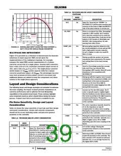
TM
Placing NTC in close proximity to the
output inductor of VR0’s Channel 1 and to
the output rail, not close to MOSFET side
(see Figure 23); the return trace should be
25 mils away from other traces. Place 1k
pull-up and decoupling capacitor (typically
0.1µF) in close proximity to the controller.
The pull-up resistor should be exactly tied
to the same point as VCC pin, not through
an RC filter. If not used, connect this pin to
TMS or 1M Ω/2M Ω resistor divider, but
DON’T tie it to VCC or GND.
General
Comments
The layer next to the Top or Bottom layer is
preferred to be ground players, while the
signal layers can be sandwiched in the
ground layers if possible.
Component Placement
SICI
No
Program SI (standard-inductor, tied to
GND) and CI (coupled inductor, tied to
VCC). It is reserved for IAUTO in
ISL6366A/67 and will be noise sensitive;
SI and CI are still programmable with this
pin.
Within the allotted implementation area, orient the switching
components first. The switching components are the most critical
because they carry large amounts of energy and tend to generate
high levels of noise. Switching component placement should take
into account power dissipation. Align the output inductors and
MOSFETs such that space between the components is minimized
while creating the PHASE plane. Place the Intersil MOSFET driver
IC as close as possible to the MOSFETs they control to reduce the
parasitic impedances due to trace length between critical driver
input and output signals. If possible, duplicate the same
RSET
Yes
Yes
Placing the R in close proximity to the
controller. DON’T use decoupling capacitor
on this pin.
FS_DRP
Placing the R in close proximity to the
controller. Must tie GND or VCC via 1MΩ
when VR0 is not in use. Don’t use
decoupling capacitor on this pin.
placement of these components for each phase.
Next, place the input and output capacitors. Position the high-
frequency ceramic input capacitors next to each upper MOSFET
drain. Place the bulk input capacitors as close to the upper
MOSFET drains as dictated by the component size and
dimensions. Long distances between input capacitors and
MOSFET drains result in too much trace inductance and a
reduction in capacitor performance. Locate the output capacitors
between the inductors and the load, while keeping them in close
proximity to the microprocessor socket.
VCC
Yes
NO
Place the decoupling capacitor in close
proximity to the controller.
PWM1-6
Avoid the respective PWM routing across
or under other phase’s power
trains/planes and current sensing
network. Don’t make them across or under
external components of the controller. At
least 20mils away from any other traces.
To improve the chance of first pass success, it is very important
to take time to follow the above outlined design guidelines and
Intersil generated layout check list, see more details in “Voltage-
Regulator (VR) Design Materials” on page 42. Proper planning for
the layout is as important as designing the circuits. Running
things in a hurry, you could end up spending weeks and months
to debug a poorly-designed and improperly laid out board.
EN_VTT
No
There is an internal 1µs filter. Decoupling
capacitor is not needed, but if needed, use
a low timing constant one to avoid too
much shut-down delay.
ISEN[6:1]+
Yes
Connect to the output rail side of the
respective channel’s output inductor or
resistor pin. Decoupling is optional and
might be required for long sense traces
and a poor layout.
FN6964.0
January 3, 2011
41

 INTERSIL [ Intersil ]