ISL6366
designer to reduce the cost of input capacitors. The example in
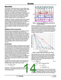
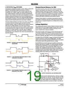
Figure 3 illustrates input currents from a three-phase converter
combining to reduce the total input ripple current.
10
5 ⋅ 10 ⋅ V
IN
V
= ---------------------------------------------
(EQ. 3)
RAMP
F
⋅ R
SW
RAMP_ADJ
With EAPP control and feedforward function, the ISL6366 can
achieve excellent transient performance over wide frequency
range of load step, resulting in lower demand on the output
capacitors.
INPUT-CAPACITOR CURRENT, 10A/DIV
At DC load conditions, the PWM frequency is constant and set by
the external resistor between the FS pin and GND during normal
mode (PSI0) and low power mode (PSI1). However, when PSI2 or
PSI3 is asserted in ultra low power conditions and if the VR is
configured into diode emulation operation, the EAPP reduces the
switching frequency as the load decreases. Thus, the VR can
enter burst mode at extreme light load conditions and improve
power conversion efficiency significantly.
CHANNEL 1
INPUT CURRENT
10A/DIV
CHANNEL 2
INPUT CURRENT
10A/DIV
CHANNEL 3
INPUT CURRENT
10A/DIV
Under steady state conditions, the operation of the ISL6366
PWM modulator appears to be that of a conventional trailing
edge modulator. Conventional analysis and design methods can
therefore be used for steady state and small signal operation.
1µs/DIV
FIGURE 3. CHANNEL INPUT CURRENTS AND INPUT-CAPACITOR
RMS CURRENT FOR 3-PHASE CONVERTER
The single-phase PWM has a fix ramp of 2V peak to peak. Its
overall modulation gain is proportional to the input line.
The converter depicted in Figure 3 delivers 36A to a 1.5V load from
a 12V input. The RMS input capacitor current is 5.9A. Compare this
to a single-phase converter also stepping down 12V to 1.5V at 36A.
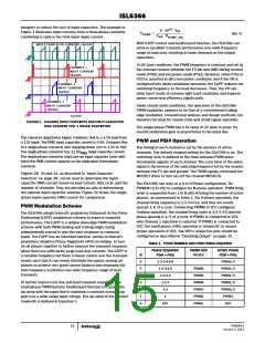
PWM and PSI# Operation
The timing of each channel is set by the number of active
channels. The default channel setting for the ISL6366 is six. The
switching cycle is defined as the time between PWM pulse
termination signals of each channel. The cycle time of the pulse
signal is the inverse of the switching frequency set by the resistor
between the FS pin and ground. The PWM signals command the
MOSFET driver to turn on/off the channel MOSFETs.
The single-phase converter has 11.9A
input capacitor current.
RMS
The single-phase converter must use an input capacitor bank with
twice the RMS current capacity as the equivalent three-phase
converter.
Figures 29, 30 and 31, as described in “Input Capacitor
Selection” on page 38, can be used to determine the input
capacitor RMS current based on load current, duty cycle, and the
number of channels. They are provided as aids in determining
the optimal input capacitor solution. Figure 32 shows the single
phase input-capacitor RMS current for comparison.
The ISL6366 can work in a 0 to 6-Phase configuration. Tie
PWM(N+1) to VCC to configure for N-phase operation. PWM firing
order is sequential from 1 to N with N being the number of active
phases, as summarized in Table 1. For 6-phase operation, the
channel firing sequence is 1-2-3-4-5-6, and they are evenly
spaced 1/6 of a cycle. Connecting PWM6 to VCC configures
5-phase operation, the channel firing order is 1-2-3-4-5 and the
phase spacing is 1/5 of a cycle. If PWM2 is connected to VCC,
only Channel 1 operation is selected. If PWM1 is connected to
VCC, the multi-phase (VR0) operation is turned off; to ensure
proper operation of VR1, the VR0’s respective pins should be
configured as described in “Disabling Output” on page 35.
PWM Modulation Scheme
The ISL6366 adopts Intersil's proprietary Enhanced Active Pulse
Positioning (EAPP) modulation scheme to improve transient
performance. The EAPP is a unique dual-edge PWM modulation
scheme with both PWM leading and trailing edges being
independently moved to give the best response to transient
loads. The EAPP has an inherited function, similar to Intersil's
proprietary Adaptive Phase Alignment (APA) technique, to turn
on all phases together to further improve the transient response,
when there are sufficiently large load step currents. The EAPP is
a variable frequency but there is linear control over the transient
events such that it can evenly distribute the pulses among all
phases to achieve very good current balance and eliminate the
beat frequency oscillation over wide frequency range of load
transients.
TABLE 1. PHASE NUMBER AND PWM FIRING SEQUENCE
PHASE SEQUENCE
PSI# = PSI0
PWM# TIED
TO VCC
ACTIVE PHASE
PSI# = PSI1
N
6
5
4
3
2
1
0
1-2-3-4-5-6
1-2-3-4-5
1-2-3-4
1-2-3
-
PWM1/4
PWM1/3
PWM1/3
PWM1/2
PWM1/2
PWM1
PWM6
PWM5
PWM4
PWM3
PWM2
PWM1
To further improve the line and load transient responses, the
multi-phase PWM features feedforward function to change the
up ramp with the input line to maintain a constant overall loop
gain over a wide range input voltage. The up ramp of the internal
Sawtooth is defined in Equation 3.
1-2
1
OFF
OFF
FN6964.0
January 3, 2011
15

 INTERSIL [ Intersil ]