ISL6366
IMAXS - An input pin to set the maximum current, I
,
BT_FDVID_TCOMP (0E):
CCMAX
register of the VR1. It can be programed to 20A, 25A, 30A, and
35A when the droop is enabled (R = GND). This register
BT - An input pin to set the start-up boot voltage register of VR0.
It has four levels: 0V, 0.9V, 1.0V, and 1.1V for core applications.
When the droop is disabled, the boot levels will be changed to 0V,
1.2V, 1.35V, and 1.5V for memory applications.
FSS_DRPS
represents the maximum allowed load current for VR1 and
corresponds to a 900mV (typically set) at IMONS. When VR1
droop is disabled (R
= VCC), the I can be
FSS_DRPS
CCMAX
programed to15A, 20A, 25A, and 30A.
FDVID - An input pin to set the slew rate of fast Dynamic VID. It
has choices of 10mV/µs and 20mV/µs. This will only apply to
VR0, not VR1.
TMAX - An input pin to set the maximum temperature register
(TMAX) of the VR0 and VR1 and the thermal trip point of
VR_HOT#. It covers +90°C to +120°C with 5°C/step. The
register represents the maximum allowed temperature of VR0
and VR1, and programs the over-temperature trip point at
VR_HOT#. The typical application should use +100°C or lower
since the NTC thermistor temperature represents the PCB, not
the hottest component on the board. In addition, the NTC
thermistor typically picks up a temperature lower than the PCB
due to the thermal impedance between PCB and NTC.
TCOMP - An input to set the mis-matching temperature (+13°C to
+43°C) between the actual sensed inductor of VR0 regulator and
the NTC thermistor at the TM pin. The voltage sensed on the TM pin
is utilized as the temperature input to adjust the droop current and
the overcurrent protection limit to effectively compensate for the
temperature coefficient of the current sense element of VR0. To
implement the integrated temperature compensation, select a
proper temperature offset “TCOMP,” other than the “OFF” value,
which is to disable the integrated temperature compensation
function.
BTS_DES_TCOMPS (0D):
BTS - An input pin to set the start-up boot voltage register of VR1.
It has four levels: 0, 0.9V, 1.0, and 1.1V for graphic rails with
NSPI_DE_IMAX (0F):
droop enabled (R
(R
FSS_DRPS
= GND). When the droop is disabled
= VCC), the boot levels will be changed to 0, 0.85V,
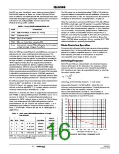
NPSI - An input pin to set the number of phases dropping at low
power mode. See Table 3 on page 16 for more details.
FSS_DRPS
0.925V, 1.05V for VCCIO and System Agent rails.
DE - An input pin to set the diode emulation (DE) operation
register of VR0 at PSI2, PSI3, and Decay modes. At PSI1 mode,
the VR0 always operates in CCM mode. When the diode
emulation is disabled, the output will decay at the rate of setVID
Slow; however, the SVID bus is still be acknowledged of execution
of the command.
DES - An input pin to set the diode emulation (DE) operation
register of VR1 at PSI2, PSI3, and Decay modes. At PSI1 mode,
the VR1 always operates in CCM mode. When the diode
emulation is disabled, the output will decay at the rate of setVID
Slow; however, the SVID bus is still be acknowledged of execution
of the command.
IMAX - An input pin to set the maximum current, I
, register
CCMAX
TCOMPS - An input pin to set the mis-matching temperature
(+13°C to +43°C) between the actual sensed inductor and the NTC
thermistor at TMS pin. The voltage sensed on the TMS pin is utilized
as the temperature input to adjust the droop current and the
overcurrent protection limit to effectively compensate for the
temperature coefficient of the current sense element of VR1. To
implement the integrated temperature compensation, select a
proper temperature offset “TCOMP,” other than the “OFF” value,
which is to disable the integrated temperature compensation
function. When the VR1 channel’s droop is disabled by pulling
FSS_DRPS pin high with a frequency set resistor, TCOMPS register
will be used to set the address of PMBus, 80-8Eh for VR0 and E0-
EEh for VR1 in ISL6367.
of the VR0 voltage regulator. It has a range of 15A to 165A with
5A/step. In 5- and 6-Phase operation, it will add 90A offset over
the previous range and cover the range of 105A to 255A with
5A/step. This register represents the maximum allowed load
current for VR0 and corresponds to a 900mV (typically set) at
IMON.
NC[1:3] - No connection pins for ISL6366 and ISL6366A.
Reserved for PMBus [I2DATA, PMALERT#, I2CLK] in ISL6367.
NC[4:5] - No connection pins for ISL6366. Reserved for input
current sensing [ISENIN-, ISENIN+] in ISL6366A and ISL6367.
FN6964.0
January 3, 2011
13

 INTERSIL [ Intersil ]