ISL6366
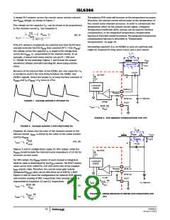
A simple R-C network across the current sense resistor extracts
the R voltage, as shown in Figure 7.
The inductor DCR value will increase as the temperature increases.
Therefore, the sensed current will increase as the temperature of
the current sense element increases. In order to compensate the
temperature effect on the sensed current signal, a Negative
Temperature Coefficient (NTC) resistor can be used for thermal
compensation, or the integrated temperature compensation
function of ISL6366 should be utilized. The integrated temperature
compensation function is described in “Temperature
Compensation” on page 30.
SEN
The voltage on the capacitor V , can be shown to be proportional
C
to the channel current I . See Equation 9.
L
ESL
⎛
⎝
⎞
-------------
s ⋅
+ 1 ⋅ (R
⋅ I )
SEN L
(EQ. 9)
⎠
R
SEN
V (s) = --------------------------------------------------------------------
C
(s ⋅ RC + 1)
If the R-C network components are selected such that the RC time
constant matches the ESL-R time constant (R*C = ESL/R ),
Decoupling capacitor (C ) on ISEN[6:1]- pins are optional and
T
might be required for long sense traces and a poor layout.
SEN SEN
the voltage across the capacitor V is equal to the voltage drop
C
I
(s)
across the R
, i.e., proportional to the channel current. As an
L
SEN
example, a typical 1mΩ sense resistor can use R = 348 and
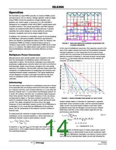
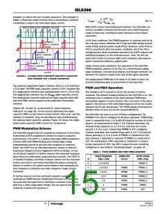
C = 820pF for the matching. Figures 7 and 8 show the sensed
waveforms without and with matching RC when using resistive
sense.
L
DCR
V
OUT
INDUCTOR
-
C
OUT
V
L
Because of the internal filter at the ISENS- pin, one capacitor, C ,
T
is needed to match the time delay between the ISENS- and
-
(s)
V
C
ISL6366
ISENS+ signals. Select the proper C to keep the time constant of
R
C
T
I
n
R
and C (R
x C ) close to 27ns.
ISEN T
ISEN
T
CURRENT
SENSE
ISEN-(n)
+
-
R
ISEN(n)
C , Optional
T
ISEN+(n)
RSET
FIGURE 7. VOLTAGE ACROSS R WITHOUT RC
DCR ⋅ 64
I
-----------------------
= I
SEN
L
R
SET
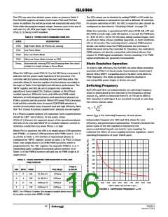
FIGURE 9. DCR SENSING CONFIGURATION FOR VR0
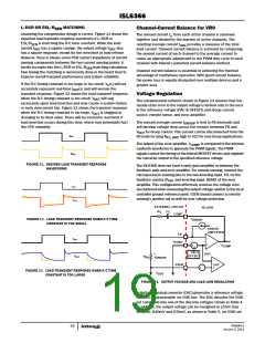
FIGURE 8. VOLTAGE ACROSS C WITH MATCHING RC
I
L
Equation 10 shows that the ratio of the channel current to the
L
sensed current, I
, is driven by the value of the sense resistor
R
ESL
V
SEN
SEN
OUT
and the R
.
ISEN
R
R
C
SENSE
OUT
-
SEN
V
(EQ. 10)
R
---------------
I
= I ⋅
-
SEN
L
R
R
V
(s)
C
ISEN
Figures 5 and 6 configurations apply for VR1 output, while the
should include the internal metal impedance of 10.5Ω for
accurate current sense.
C
ISL6366
R
ISEN
I
n
For VR0 output, the R
ISEN
while its value is determined by the R
resistor of each channel is integrated,
resistor. The RSET resistor
CURRENT
SENSE
SET
value can be from 3.84kΩ to 115.2kΩ and is 64x of the required
resistor value. Therefore, the current sense gain resistor
+
-
R
ISEN(n)
ISEN-(n)
I
SEN
(Integrated R
) value can be effectively set at 60Ω to 1.8kΩ.
ISEN
ISEN+(n)
RSET
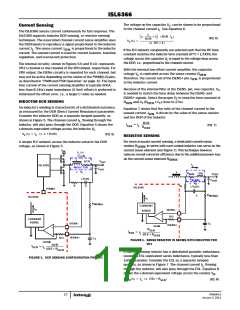
Figures 9 and 10 show the configurations for inductor DCR sensing
and resistive sensing of VR0, respectively; their sensing current is
represented by Equations 11 and 12, respectively.
DCR ⋅ 64
R
⋅ 64
SEN
I
C , Optional
-------------------------
= I
T
SEN
L
R
SET
(EQ. 11)
-----------------------
I
= I ⋅
SEN
L
R
SET
FIGURE 10. SENSE RESISTOR IN SERIES WITH INDUCTORS FOR
VR0
R
⋅ 64
SEN
R
-------------------------
I
= I ⋅
(EQ. 12)
SEN
L
SET
FN6964.0
January 3, 2011
18

 INTERSIL [ Intersil ]