ISL6366
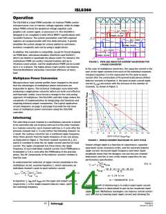
The voltage on the capacitor V , can be shown to be proportional
Current Sensing
C
to the channel current I . See Equation 6.
L
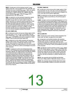
The ISL6366 senses current continuously for fast response. The
ISL6366 supports inductor DCR sensing, or resistive sensing
techniques. The associated channel current sense amplifier uses
the ISEN inputs to reproduce a signal proportional to the inductor
L
⎛
⎝
⎞
-----------
s ⋅
+ 1 ⋅ (DCR ⋅ I )
L
⎠
(EQ. 6)
DCR
----------------------------------------------------------------
V (s) =
C
(s ⋅ RC + 1)
current, I . The sense current, I
current. The sensed current is used for current balance, load-line
regulation, and overcurrent protection.
, is proportional to the inductor
L
SEN
If the R-C network components are selected such that the RC time
constant matches the inductor time constant (R*C = L/DCR), the
voltage across the capacitor V is equal to the voltage drop across
C
the DCR, i.e., proportional to the channel current.
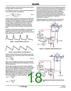
The internal circuitry, shown in Figures 5-6 and 9-10, represents
VR1’s channel or one channel of the VR0 output, respectively. For
VR0 output, the ISEN± circuitry is repeated for each channel, but
may not be active depending on the status of the PWM[6:2] pins,
as described in “PWM and PSI# Operation” on page 15. The input
bias current of the current sensing amplifier is typically 60nA;
less than 8.34kΩ input impedance (0.5mV offset) is preferred to
minimized the offset error, i.e., a larger C value as needed.
With the internal low-offset current amplifier, the capacitor
voltage V is replicated across the sense resistor R
.
C
ISEN
, is proportional
Therefore, the current out of the ISENS+ pin, I
to the inductor current.
SEN
Because of the internal filter at the ISENS- pin, one capacitor, C ,
T
is needed to match the time delay between the ISENS- and
ISENS+ signals. Select the proper C to keep the time constant of
T
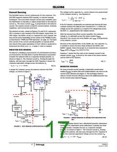
INDUCTOR DCR SENSING
R
and C (R x C ) close to 27ns.
ISEN
T
ISEN T
An inductor’s winding is characteristic of a distributed resistance,
as measured by the DCR (Direct Current Resistance) parameter.
Consider the inductor DCR as a separate lumped quantity, as
Equation 7 shows that the ratio of the channel current to the
sensed current, I , is driven by the value of the sense resistor
and the DCR of the inductor.
SEN
shown in Figure 5. The channel current I , flowing through the
L
DCR
---------------
= I ⋅
L
inductor, will also pass through the DCR. Equation 5 shows the
I
(EQ. 7)
SEN
R
ISEN
s-domain equivalent voltage across the inductor V .
L
V (s) = I ⋅ (s ⋅ L + DCR)
(EQ. 5)
L
L
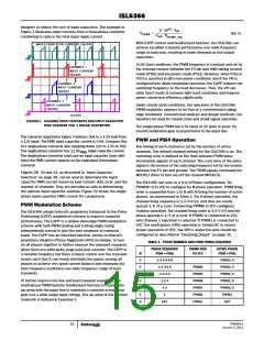
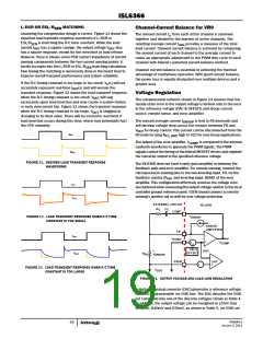
RESISTIVE SENSING
For more accurate current sensing, a dedicated current-sense
resistor R in series with each output inductor can serve as the
A simple R-C network across the inductor extracts the DCR
voltage, as shown in Figure 5.
SENSE
current sense element (see Figure 7). This technique however
reduces overall converter efficiency due to the additional power loss
V
IN
I
(s)
L
on the current sense element R
.
L
SENSE
DCR
V
OUT
I
ISL6596
L
INDUCTOR
-
C
OUT
V
L
L
R
ESL
V
SEN
R
OUT
-
(s)
V
C
C
SENSE
OUT
-
-
V
R
(s)
R
C
R
V
C
ISL6366
PWMS
R
C
ISEN(n)
ISL6366
I
n
R
ISEN(n)
CURRENT
SENSE
I
n
ISENS-
10.5
+
-
CURRENT
SENSE
ISENS-
ISENS+
C
T
ISENS+
+
-
R
SEN
I
---------------------------------
= I
SEN
L
10.5 + R
ISEN
10.5
C
T
FIGURE 6. SENSE RESISTOR IN SERIES WITH INDUCTOR FOR
VR1
DCR
I
---------------------------------
= I
SEN
L
10.5 + R
ISEN
A current sensing resistor has a distributed parasitic inductance,
known as ESL (equivalent series inductance, typically less than
1nH) parameter. Consider the ESL as a separate lumped
FIGURE 5. DCR SENSING CONFIGURATION FOR VR1
quantity, as shown in Figure 7. The channel current I , flowing
L
through the inductor, will also pass through the ESL. Equation 8
shows the s-domain equivalent voltage across the resistor V .
R
V (s) = I ⋅ (s ⋅ ESL + R )
SEN
(EQ. 8)
R
L
FN6964.0
January 3, 2011
17

 INTERSIL [ Intersil ]