ISL6366
Operation
The ISL6366 is a dual PWM controller; its 6-phase PWMs control
microprocessor core or memory voltage regulator, while its single-
phase PWM controls the peripheral voltage regulator such
graphics rail, system agent, or processor I/O. The ISL6366 is
designed to be compliant to Intel VR12/IMVP7 specifications with
SerialVID Features. The system parameters and SVID required
registers are programmable with four dedicated pins. It greatly
simplifies the system design for various platforms and lowers
inventory complexity and cost by using a single device.
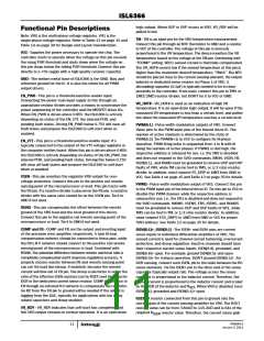
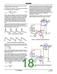
IL1 + IL2 + IL3, 7A/DIV
IL1, 7A/DIV
PWM1, 5V/DIV
IL2, 7A/DIV
PWM2, 5V/DIV
IL3, 7A/DIV
PWM3, 5V/DIV
In addition, this controller is compatible, except for forced dropping
via PWM lines, with phase doublers (ISL6611A and ISL6617),
which can double or quadruple the phase count. For instance, the
multi-phase PWM can realize a beyond 6-phase and up to
24-phase count system, and the single-phase PWM can be scaled
up to 2 or 4 phases. The higher phase count system can improve
thermal distribution and power conversion efficiency at heavy
load.
1µs/DIV
FIGURE 1. PWM AND INDUCTOR-CURRENT WAVEFORMS FOR
3-PHASE CONVERTER
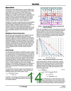
In the case of multiphase converters, the capacitor current is the
sum of the ripple currents from each of the individual channels.
Compare Equation 1 to the expression for the peak-to-peak
current after the summation of N symmetrically phase-shifted
inductor currents in Equation 2, the peak-to-peak overall ripple
Multiphase Power Conversion
Microprocessor load current profiles have changed to the point
that the advantages of multiphase power conversion are
impossible to ignore. The technical challenges associated with
producing a single-phase converter (which are both cost-effective
and thermally viable), have forced a change to the cost-saving
approach of multiphase. The ISL6366 controller helps reduce the
complexity of implementation by integrating vital functions and
requiring minimal output components. The typical application
circuits diagrams on page 5 and page 6 provide the top level
views of multiphase power conversion using the ISL6366
controller.
current (I
channels, as shown in Figure 2.
) decreases with the increase in the number of
C,PP
N=1
2
3
Interleaving
4
5
The switching of each channel in a multiphase converter is timed
to be symmetrically out-of-phase with each of the other channels.
In a 3-phase converter, each channel switches 1/3 cycle after the
previous channel and 1/3 cycle before the following channel. As
a result, the 3-phase converter has a combined ripple frequency
three times greater than the ripple frequency of any one phase,
as illustrated in Figure 1. The three channel currents (IL1, IL2,
and IL3) combine to form the AC ripple current and the DC load
current. The ripple component has three times the ripple
frequency of each individual channel current. Each PWM pulse is
terminated 1/3 of a cycle after the PWM pulse of the previous
phase. The DC components of the inductor currents combine to
feed the load.
6
DUTY CYCLE (V /V )
OUT IN
FIGURE 2. RIPPLE CURRENT MULTIPLIER VS. DUTY CYCLE
Output voltage ripple is a function of capacitance, capacitor
equivalent series resistance (ESR), and the summed inductor
ripple current. Increased ripple frequency and lower ripple
amplitude mean that the designer can use less per-channel
inductance and few or less costly output capacitors for any
performance specification.
To understand the reduction of ripple current amplitude in the
multiphase circuit, examine Equation 1, which represents an
individual channel’s peak-to-peak inductor current.
V
OUT
(EQ. 2)
------------------
I
=
K
C, PP
RCM
L ⋅ F
SW
(N ⋅ D – m + 1) ⋅ (m – (N ⋅ D))
---------------------------------------------------------------------------
=
K
RCM
N ⋅ D
(V – V
) ⋅ V
OUT
⋅ V
IN
IN
OUT
(EQ. 1)
I
= ---------------------------------------------------------
PP
L ⋅ F
for
m – 1 ≤ N ⋅ D ≤ m
SW
m = ROUNDUP(N ⋅ D, 0)
In Equation 1, V and V
IN OUT
are the input and output voltages
respectively, L is the single-channel inductor value, and F
the switching frequency.
is
SW
Another benefit of interleaving is to reduce input ripple current.
Input capacitance is determined in part by the maximum input
ripple current. Multiphase topologies can improve overall system
cost and size by lowering input ripple current and allowing the
FN6964.0
January 3, 2011
14

 INTERSIL [ Intersil ]