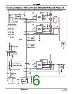
ISL6366
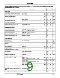
Electrical Specifications Recommended Operating Conditions, V = 5V, Unless Otherwise specified. Boldface limits apply over the
CC
operating temperature range. (Continued)
MIN
MAX
PARAMETER
TEST CONDITIONS
(Note 7) TYP (Note 7) UNITS
VR0 Peak Current Limit for Individual Channel
VR1 Average Overcurrent Trip Level
IMON, IMOS Clamped and OCP Trip Level
IMON, IMONS VOLTAGE IMAX (FF) TRIP POINT
THERMAL MONITORING
-
-
139
100
1.12
880
-
µA
µA
V
CS Offset and Mirror Error Included, R
= 100Ω
-
ISENS
1.085
875
1.14
887
Higher than this will be “FF”
mV
VR_HOT# Pull-down Impedance
8.4
-
9.2
13
-
Ω
TM Voltage at Thermal Trip (Programmable via
TMAX)
TMAX = +100°C, see Table 7
39.12
%VCC
VR_HOT# and Thermal Alert# Hysteresis
Leakage Current of VR_HOT#
-
-
3
-
-
°C
µA
With external pull-up resistor connected to VCC
1
VR READY AND PROTECTION MONITORS
Leakage Current of VR_RDY, VR_RDYS
VR READY Low Voltage
With pull-up resistor externally connected to VCC
4mA Load
-
-
1
0.3
-
µA
V
-
-
-
Overvoltage Protection Threshold
Prior to the End of Soft-start
2.30
179
107
V
After the End of Soft-start, the voltage above VID
160
98
200
117
mV
mV
Overvoltage Protection Reset Hysteresis
SVID BUS
ALERT# Pull-down Impedance
SVDATA
-
-
-
-
11
11
13
Ω
13
Ω
SVCLK Maximum Speed
SVCLK Minimum Speed
NOTES:
26.5
13.0
-
-
MHz
MHz
6. These parts are designed and adjusted for accuracy with all errors in the voltage loop included.
7. Compliance to datasheet limits is assured by one or more methods: production test, characterization and/or design.
FN6964.0
January 3, 2011
10

 INTERSIL [ Intersil ]