HSP50110
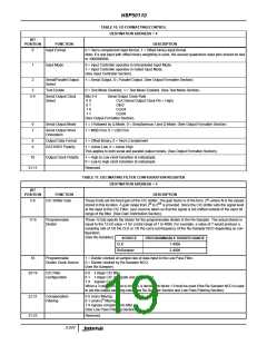
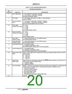
TABLE 13. PHASE OFFSET REGISTER
DESTINATION ADDRESS = 7
BIT
POSITION
FUNCTION
Phase Offset
DESCRIPTION
7-0
This 8 bit two’s complement value specifies a carrier phase offset of π(n/128) where n is the two’s com-
plement value. This provides a range of phase offsets from -π to π*(127/128). (See Synthesizer/Mixer
Section).
31-8
Reserved.
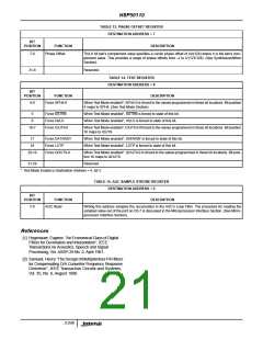
TABLE 14. TEST REGISTER
DESTINATION ADDRESS = 8
BIT
POSITION
FUNCTION
Force SPH4-0
DESCRIPTION
4-0
When Test Mode enabled*, SPH4-0 is forced to the values programmed in these bit locations. Bit position
4 maps to SPH4. (See Test Mode Section).
5
6
Force SSTRB
Force HI/LO
When Test Mode enabled*, SSTRB is forced to state of this bit.
When Test Mode enabled*, HI/LO is forced to state of this bit.
16-7
Force IOUT9-0
When Test Mode enabled*, IOUT9-0 if forced to the values programmed in these bit locations. Bit position
16 maps to IOUT9.
17
18
Force DATARDY
Force LOTP
When Test Mode enabled*, DATARDY is forced to state of this bit.
When Test Mode enabled*, LOTP is forced to state of this bit.
28-19
Force QOUT9-0
When Test Mode enabled*, QOUT9-0 is forced to the values programmed in these bit locations. Bit posi-
tion 16 maps to QOUT9.
31-29
Reserved.
* Test Mode Enable is Destination Address = 4, bit-3.
TABLE 15. AGC SAMPLE STROBE REGISTER
DESTINATION ADDRESS = 9
BIT
POSITION
FUNCTION
AGC Read
DESCRIPTION
7-0
Writing this address samples the accumulator in the AGC’s Loop Filter. The procedure for reading the
sampled value out of the part on C0-7 is discussed in the Microprocessor Interface Section. (See Micro-
processor Interface Section).
References
[1] Hogenauer, Eugene, “An Economical Class of Digital
Filters for Decimation and Interpolation”, IEEE
Transactions on Acoustics, Speech and Signal
Processing, Vol. ASSP-29 No. 2, April 1981.
[2] Samueli, Henry “The Design of Multiplierless FIR filters
for Compensating D/A Converter Frequency Response
Distortion”, IEEE Transaction Circuits and Systems,
Vol. 35, No. 8, August 1988.
3-249

 INTERSIL [ Intersil ]