HSP50110
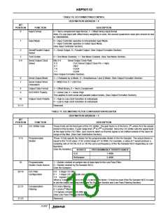
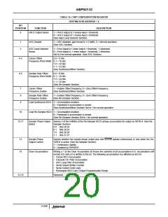
TABLE 12. CHIP CONFIGURATION REGISTER
DESTINATION ADDRESS = 6
BIT
POSITION
FUNCTION
DESCRIPTION
0
HI/LO Output Sense
1 = HI/LO output of 1 means input > threshold.
0 = HI/LO output of 1 means input ≤ threshold.
(See Input Level Detector Section).
1
2
AGC Disable
1 = AGC disabled, gain forced to 1.0 (0dB), 0 = Normal operation.
(See AGC Section).
AGC Level Detector
Sense
1 = Error signal is 1 when output > threshold, -1 otherwise.
0 = Error signal is -1 when output > threshold, 1 otherwise.
Set to 0 for normal operation. (See AGC Section).
4-3
6-5
Carrier Offset
Frequency Word Width 0 1 = 16 bits
1 0 = 24 bits
0 0 = 8 bits
1 1 = 32 bits
(See Synthesizer/Mixer Section).
Sample Rate Offset
0 0 = 8 bits
Frequency Word Width 0 1 = 16 bits
1 0 = 24 bits
1 1 = 32 bits
(See Re-Sampler Section).
7
8
9
Carrier Offset
Frequency Enable
1 = Enable Offset Frequency, 0 = Zero Offset Frequency.
(See Synthesizer/Mixer Section).
Sample Rate Offset
Frequency Enable
1 = Enable Offset Frequency, 0 = Zero Offset Frequency.
(See Re-Sampler Section).
Load Synthesizer NCO 1 = Accumulation enabled.
0 = Feedback in accumulator is zeroed.
(See Synthesizer/Mixer Section) Set to 1 for normal operation.
10
Load Re-Sampler NCO 1 = Accumulation enabled.
0 = Feedback in accumulator is zeroed.
(See Re-Sampler Section) Set to 1 for normal operation.
12-11
Sample Phase Output Selects 5 of the 8 MSBs of the Re-Sampler NCO’s phase accumulator for output on SPH0-4. (See Re-
Select
Sampler Section).
0 0 Bits 28:24.
0 1 Bits 29:25.
1 0 Bits 30:26.
1 1 Bits 31:27.
13
14
Sample Phase
Output Control
Selects whether the sample phase output pins and SSTRB update continuously or only when the DA-
TARDY is active. (See Re-Sampler Section).
1 = Continuous Update.
0 = Updated by DATARDY.
Clear Accumulators
Writing a 1 to the Clear Accumulator bit forces the contents of all accumulators to 0. Accumulators will
remain at 0 until a 0 is written to this bit. The following accumulators are affected by this bit.
• Carrier NCO Accumulator
• Cascode CIC Filter Accumulator
• AGC Loop Filter Accumulator
• Serial Output Shifter Counter
• Serial Output Clock Logic
• ReSampler NCO Carry Output Programmable Divider
31-15
Reserved.
3-248

 INTERSIL [ Intersil ]