HSP50110
l
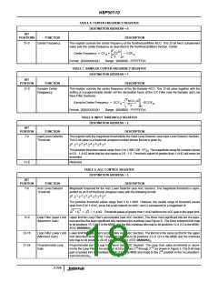
TABLE 6. CENTER FREQUENCY REGISTER
DESTINATION ADDRESS = 0
BIT
POSITIONS
FUNCTION
DESCRIPTION
31-0
Center Frequency
This register controls the center frequency of the Synthesizer/Mixer NCO. This 32-bit two’s complement
value sets the center frequency as described in the Synthesizer/Mixer Section. Center
F
32
C
F
S
˙
– COF
H
-------
Center Frequency = CF
=
2
H
H
Format: [XXXXXXXX]H
Range: (0000000 - FFFFFFF)H.
TABLE 7. SAMPLER CENTER FREQUENCY REGISTER
DESTINATION ADDRESS = 1
BIT
POSITION
FUNCTION
DESCRIPTION
31-0
Sampler Center
Frequency
This register controls the center frequency of the Re-Sampler NCO. This 32-bit value together with the
setting of a programmable divider set the decimation factor of the CIC Filter (see Re-Sampler and Low
Pass Filter Sections).
F
32
NCO
F
S
---------------
SamplerCenter Frequency = SCF
=
2
–SCOF
H.
H
H
Format: [XXXXXXXX]H
Range: (0000000 - FFFFFFF)H.
TABLE 8. INPUT THRESHOLD REGISTER
DESTINATION ADDRESS = 2
BIT
POSITION
FUNCTION
DESCRIPTION
7-0
Input Level Detector
Threshold
This register sets the magnitude threshold for the Input Level Detector (see Input Level Detector Section).
This 8-bit value is a fractional unsigned number whose format is given by:
0
-1 -2 -3 -4 -5 -6 -7
2 . 2
2
2
2
2
2
2 .
The possible threshold values range from 0 to 1.9961 (00 - FF) . The magnitude range for complex inputs
H
is 0.0 - 1.4142 while that for real inputs is 0.0 - 1.0. Threshold values of greater than 1.4142 will never be
exceeded.
31-8
Reserved.
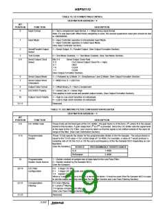
TABLE 9. AGC CONTROL REGISTER
DESTINATION ADDRESS = 3
BIT
POSITION
FUNCTION
DESCRIPTION
7-0
AGC Level Detector
Threshold
Magnitude threshold for the AGC Level Detector (see AGC Section). The magnitude threshold is repre-
sented as an 8-bit fractional unsigned value with the following format:
0
-1 -2 -3 -4 -5 -6 -7
2 . 2
2
2
2
2
2
2 .
The possible threshold values range from 0 to 1.9961. However, the usable range of threshold values
span from 0 to 1.4142, since full scale outputs on both I and Q correspond to a magnitude of
2
2
I
+ Q
=
2 = 1.4142 . Threshold values of greater than 1.4142 will force the AGC gain to the upper limit.
15-8
Loop Filter Upper Limit Upper limit for Loop Filter’s accumulator (see AGC Section). The three most significant bits are the expo-
(Maximum Gain)
nent and the five least significant bits represent the mantissa (see Figure 3). The three exponent bits map
to bit positions 15-13 (15 is the MSB) and the five mantissa bits map to bit positions 12-8 (12 is the MSB).
(EEE.MMMMM)
2.
23-16
31-24
Loop Filter Lower Limit Lower limit for Loop Filter’s accumulator (see AGC Section). The format is the same as that for the upper
(Minimum Gain)
limit described above. The 3 exponent bits map to bit positions 23-21 (23 is the MSB) and the mantissa
bits map to bit positions 20-16 (20 is the MSB). (EEE.MMMMM)
2.
Programmable Loop
Gain
Programmable part of Loop Gain word (see AGC Section). The Loop Gain value increments or decre-
-6 -13
ments the Loop Filter’s Accumulator at bit positions 2 through 2
gain is loaded into bit positions 31-24 (31 is the MSB and maps to the 2 position in the Accumulator).
(GGGGGGGG)
as shown in Figure 3. The 8-bit loop
-6
2.
3-246

 INTERSIL [ Intersil ]