HSP50110
Thus, the minimum input signal will be -21.66dB below full
scale (-9.66 -12 for A/D Backoff). As before the maximum
input signal in the absence of noise is -12dB down due to
A/D backoff.
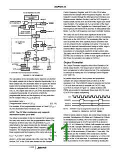
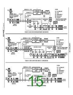
Basic Architectural Configurations
Detailed architectural diagrams are presented in Figures 18
through 20 for the basic configurations, Integrate/Dump filtering
with optional compensation, 3rd Order CIC filtering with
optional compensation, and Decimating Filter bypass. Only one
of the data paths is shown since the processing on either the
inphase or quadrature legs is identical. These diagrams are
useful for determining the throughput pipeline delay or the loop
delay of the AGC as all the internal registers are shown.
From Equation 14, the gain relationships for maximum and
minimum input can be written as follows:
Min Input Level
-6.02dB ≥ -21.66 -6.02 - 216.74 + G
+ G +
SHIFTER
AGC
6
3 3
20*log((40 x 10 /32 x 10 ) )-2.27
(EQ. 21)
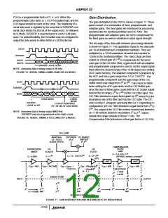
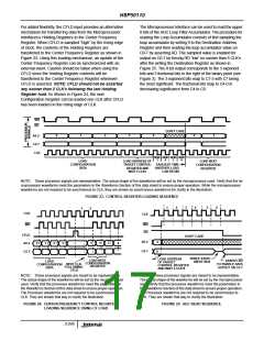
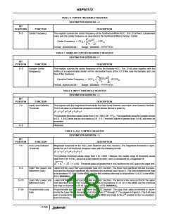
All registers with the exception of those denoted by daggers (†)
are enabled every CLK rate to minimize pipeline latency. The
registers marked by daggers are enabled at the output sample
rate as required by the filtering operation performed. The Loop
Filter accumulator in the AGC is enabled once per output
sample, and represents a delay of one output sample. The
accumulators in the CIC filter each represent a delay of one
CLK, but they are enabled for processing once per input
sample. In Interpolated Input Mode the accumulators are
enabled every CLK since the sample rate is determined by the
CLK rate (see Input Controller Section). In Gated Input Mode,
the processing delay of the accumulators is one CLK but they
are only enabled once for each sample gated into the
processing pipeline. As a result, the latency through the
accumulators is 3 CLKs rather than 3 input sample periods
when configured as a 3rd order CIC filter.
Max Input Level
-6.02dB ≤ -12 - 6.02 - 216.74 + G
+ G +
SHIFTER
AGC
3 3
6
20 x log((40 x 10 /32 x 10 ) ) -2.27
(EQ. 22)
Using the upper and lower limits found above, the gain range
can be expressed as,
45.20dB < G
AGC
+ G
SHIFTER
< 54.86dB.
(EQ. 23)
Using Equation 2 in the previous example, the shifter gain is
determined to be 2 , resulting in an AGC gain range of 3.05dB
7
< G
<12.72dB.
(EQ. 24)
AGC
3-242

 INTERSIL [ Intersil ]