HSP50110
CLK by a programmable factor of 2, 4, or 8. When the
Gain Distribution
programmable clock factor is 1, IOUT9 is pulled high, and the
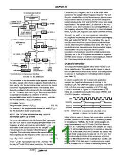
CLK signal should be used as the clock. The beginning of a
serial data word is signaled by the assertion of DATARDY one
serial clock before the first bit of the output word. In I followed
by Q Mode, DATARDY is asserted prior to each 16-bit data
word. For added flexibility, the Formatter may be configured to
output the data words in either MSB or LSB first format.
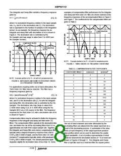
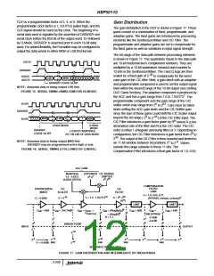
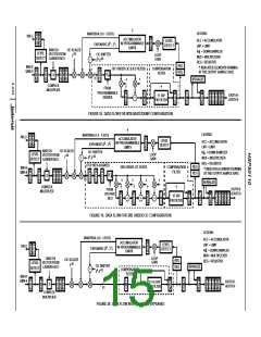
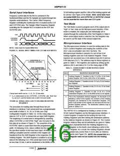
The gain distribution in the DQT is shown in Figure 17. These
gains consist of a combination of fixed, programmable, and
adaptive gains. The fixed gains are introduced by processing
elements like the Synthesizer/Mixer and CIC Filter. The
programmable and adaptive gains are set to compensate for
the fixed gains as well as variations in input signal strength.
The bit range of the data path between processing elements
is shown in Figure 17. The quadrature inputs to the data path
are 10-bit fractional two’s complement numbers. They are
multiplied by a 10-bit quadrature sinusoid and rounded to
IOUT9
DATARDY
IOUT0/
12-bits in the Synthesizer/Mixer. The I and Q legs are then
-36
scaled by a fixed gain of 2
to compensate for the worst
LSB
DATARDY LEADS 1st BIT
MSB
LSB
QOUT0
case gain of the CIC filter. Next, a gain block with an adaptive
and programmable component is used to set the output signal
level within the desired range of the 10-bit output (see Setting
DQT Gains Section). The adaptive component is produced by
NOTE: Assumes data is being output LSB first.
FIGURE 15. SERIAL TIMING (SIMULTANEOUS I/Q MODE)
7
the AGC and has a gain range from 1.0 to 1.9375*2 . The
programmable component sets the gain range of the CIC
IOUT9
0
63
shifter which may range from 2 to 2 . Care must be taken
when setting the AGC gain limits and the CIC Shifter gain
since the sum of these gains could shift the CIC Scaler output
DATARDY
IOUT0
8
-46
beyond the bit range (-2 to 2 ) of the CIC Filter input. The
MSB
LSB
0
1
MSB
N
CIC Filter introduces a gain factor given by R where R is the
I DATA WORD
Q DATA
WORD
I OUTPUT IDENTIFIED
BY 1 IN LSB OF DATA WORD
decimation rate of the filter and N is the CIC order. The CIC
order is either 1 (integrate and dump filter) or 3. Depending on
configuration, the CIC Filter introduces a gain factor from 2 to
DATARDY
LEADS 1st BIT
0
36
2
. The output of the CIC Filter is then rounded and limited to
NOTE: Assumes data is being output MSB first.
DATARDY may be programmed active high or low.
1
-9
an 11-bit window between bit positions 2 to 2 . Values
outside this range saturate to these 11 bits. The
FIGURE 16. SERIAL TIMING (I FOLLOWED BY Q MODE)
Compensation Filter introduces a final gain factor of 1.0, 0.65,
AGC GAIN
MANTISSA
1.0 - 1.9375
(0.0625 STEPS)
EXPONENT CIC BARREL
0
7
SHIFTER
2 -2
0
63
2 -2
COMPENSATION
FILTER
GAIN
SYNTHESIZER/
MIXER
CIC
SCALER
CIC
FILTER
G = 1.0, 0.65, 0.77
70
0
36
-36
3
G = 1.0 - 1.9375*2
G = 2 - 2
G = 2
G = 0.9990
(BYPASS, x/sin(x), (x/sin(x))
N
(R )
LIMIT
= 0dB
LIMIT
N
G
= 0dB
G
= -216.74dB
G
= G
G
+
G
= 20log[f /f ]
G
G
=
G
= 0dB
dB
dB
dB
dB
AGC
SHIFTER
dB
S
D
dB
dB
3
8
8
-2
N
-2
-2
= 20log[R]
0dB BYPASS
-3.74dB
-2.27dB
N = 1, 3
1
1
-2
-2
0
0
0
0
0
0
0
2
2
2
-2
2
-2
2
BINARY POINT
OUTPUT
INPUT
-1
-1
-1
-1
-1
-1
-1
2
2
2
2
2
2
2
-35
-2
-9
-10
-46
-9
-9
-9
-9
2
2
2
2
2
2
2
-46
2
RND
RND
RND
RND
G = -6.02dB
BIT RANGE OF DATA PATH
FIGURE 17. GAIN DISTRIBUTION AND INTERMEDIATE BIT WEIGHTINGS
3-240

 INTERSIL [ Intersil ]