HSP50110
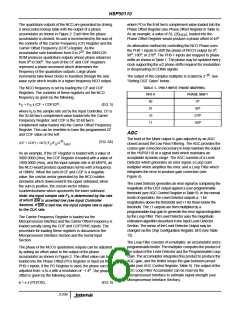
constant for decimation factors of over ~50. A summary of
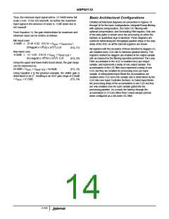
equivalent IF B ’s for different filter configurations and
N
decimation rates is given in Table 3. These noise bandwidths
are provided so that output SNR can be calculated from input
SNR. In detection applications this bandwidth indicates the
detection bandwidth.
A
B
C
D
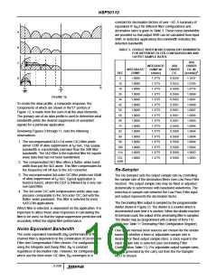
TABLE 3. DOUBLE SIDED NOISE EQUIVALENT BANDWIDTH
FOR DIFFERENT FILTER CONFIGURATIONS AND
OUTPUT SAMPLE RATES
3RD
INTEGRATE/
DUMP W/
x/sin(x)
3RD
ORDER
CIC
ORDER
CIC W/
[x/sin(x)]
INTEGRATE/
DUMP
3
DEC
2
1.0000
1.0000
1.0000
1.0000
1.0000
1.0000
1.0000
1.0000
1.0000
1.0000
1.0000
1.0000
1.0000
1.0000
1.0000
1.0000
1.3775
1.3775
1.3775
1.3775
1.3775
1.3775
1.3775
1.3775
1.3775
1.3775
1.3775
1.3775
1.3775
1.3775
1.3775
1.3775
0.6250
0.5525
0.5508
0.5504
0.5502
0.5501
0.5501
0.5501
0.5501
0.5500
0.5500
0.5500
0.5500
0.5500
0.5500
0.5500
1.3937
1.0785
1.0714
1.0698
1.0691
1.0688
1.0687
1.0686
1.0685
1.0684
1.0684
1.0684
1.0684
1.0684
1.0683
1.0683
10
18
26
34
42
50
58
66
74
82
90
98
106
114
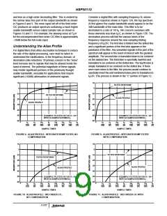
f
f
S
S
f
S
2
2R
FIGURE 12.
To create the alias profile, a composite response, the
components of which are shown in the”D” portion of
Figure 12, is made from the sum of all the alias elements.
The primary use of an alias profile is used to determine what
bandwidth yields the desired suppression of unwanted
signals for a particular application.
Reviewing Figures 9 through 11, note the following
observations:
1. The uncompensated I&D (1st order CIC) filter yields
about 12dB of alias suppression at f /16R. This usable
S
bandwidth is considerably narrower than the 3dB filter
bandwidth. The I&D filter is the matched filter for square
wave data that has not been bandlimited.
122-
4096
2. The compensated I&D filter offers a flatter, wider band-
width than just the I&D alone. This filter compensates for
the frequency roll off due to the A/D converter.
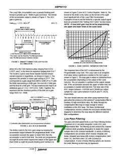
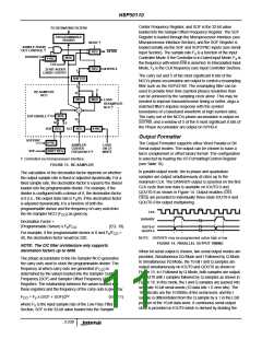
Re-Sampler
3. The uncompensated 3rd order CIC filter yields over 60dB
The Re-Sampler sets the output sample rate by controlling
the sample rate of the decimation filters (see Low Pass Filter
Section). The output sample rate may be fixed or adjusted
dynamically to synchronize with baseband waveforms. The
reduction in sample rate between the Low Pass Filter input
and output represents the decimation factor.
of alias suppression at f /16R. Typical application is
S
found in tuners, where the DQT is followed by a very nar-
row band filter.
4. The 3rd order CIC with compensation yields alias sup-
pression comparable to the 3rd order CIC, but with the
flatter, wider passband. This filter is selected for most
SATCOM applications.
The Decimating filter output is sampled by the programmable
divider shown in Figure 13. The divider is a counter which is
decremented each time it is clocked. When the divider reaches
its terminal count, the output of the decimating filter is sampled.
The divider may be programmed with a divisor of from 1 to
4096 (see Table 11 Decimating Filter Configuration Register).
Which filter is selected, is dependent on the application. It is
important to utilize these alias responses in calculating the
filter to be used, so that the signal suppression prediction will
accurately reflect the digital filter performance.
Noise Equivalent Bandwidth
One of two internal clock sources are chosen for the divider
based on whether a fixed or adjustable sample rate is
desired. For fixed output sample rates, a clock equal to the
input sample rate is selected (see Decimating Filter
Configuration Table 11). For adjustable output sample rates,
a clock generated by the carry out from the Re-Sampler
NCO is chosen.
The noise equivalent bandwidth (B ) performance of the
N
channel filter is dependent on the combination of Decimation
Filter and Compensation Filter chosen. For configurations
using the Integrate and Dump filter, B is constant
N
regardless of decimation rate. However, for configurations
which use the third order CIC filter, B converges to a
N
3-238

 INTERSIL [ Intersil ]