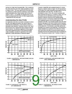
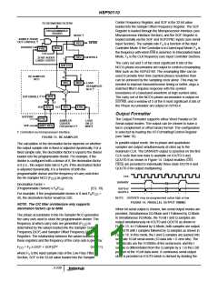
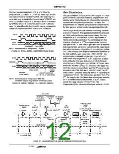
HSP50110
or 0.77 depending on whether the bypass, x/sin(x) or
(x/sin(x)) configuration is chosen. The Compensation Filter
NOTE: 10log (x) is used because these items are power
10
related.
3
output is then rounded and limited to a 10-bit output range
corresponding to bit positions 2 to 2 .
Thus, the minimum input signal will then be -42.96dB below
full scale (-30.96dB -12dB for A/D backoff). Note: in this
example the symbol rate is assumed to be one half of the
output sample rate (i.e., there are 2 samples per symbol).
0
-9
Setting DQT Gains
The AGC and CIC Shifter gains are programmed to maintain
the output signal at a desired level. The gain range required
depends on the signal levels expected at the input and the A/D
backoff required to prevent signal + noise from saturating the
A/D. The signal level at the input is based on the input SNR
which itself is derived from the either output SNR or output
The output signal is related to the input signal by:
S
= S x G
IN MIXER
x G
SCALER
x G
AGC
x
(EQ.13)
(EQ. 14)
OUT
G
x G
CIC
x G
COMP
SHIFTER
Using this equation, limits for G
AGC
and G
can be
SHIFTER
determined from the minimum and maximum input signal
conditions as given below (all gains specified in dB):
E /N . Below are two examples which describe setting the
S
0
gains using either an output SNR or E /N specification.
S
0
Min Input Level (Maximum Gain Required):
In applications based on the transmission of digital data, it is
useful to specify the DQT’s output in terms of E /N . The
following example uses this parameter and the others given in
Table 4 to show how the DQT’s gain settings can be derived.
S
0
-6.02dB ≥ -42.96 - 6.02 - 216.74 + G
+ G
+
AGC
3 3
SHIFTER
6
20 x log((40 x 10 /32 x 10 ) ) - 2.27
(EQ. 15)
Max Input Level (Minimum Input Gain Required)
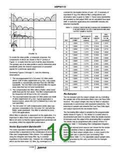
TABLE 4. EXAMPLE SYSTEM PARAMETERS
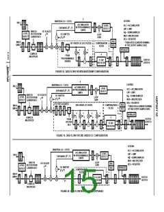
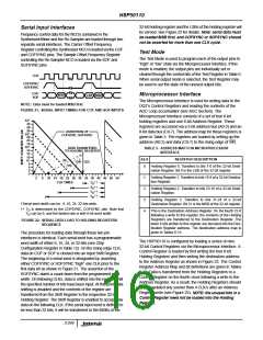
MAIN MENU
-6.02dB ≤ -12 - 6.02 - 216.74 + G
+ G +
SHIFTER
AGC
3 3
6
20 x log((40 x 10 /32 x 10 ) ) - 2.27
(EQ. 16)
PARAMETER
ITEM
SETTING
40 MSPS
32 KSPS
10MHz
-3dB
Input Sample Rate
(2)
NOTE: 20log (x) is used because these items are
10
amplitude related.
Output Sample Rate (F
) (Notes 1, 2)
(8), (9)
(10)
SOUT
Solving the above inequalities for G
gain range can be expressed as,
and G
, the
SHIFTER
AGC
Input Filter Noise Bandwidth (NBW)
Minimum Output E /N
(15)
S
0
45.20dB < (G
AGC
+ G
) < 76.16dB.
(EQ. 17)
SHIFTER
Signal + Noise Backoff at A/D Input
Output Signal Magnitude (0 to 1)
Number of CIC stages
(18), (19)
(21)
12dB
The shifter gain provides a programmable gain which is a
factor of 2. Since G ≥ 1.0, G is set as close to
the minimum gain requirement as possible:
0.5
AGC
SHIFTER
(11)
3
N
G
= 2 ,
(EQ. 18)
SHIFTER
3
Compensation Filter
(11)
(x/sin(x))
where
Noise Eq. Bandwidth of Comp. Filter
N/A
34.18kHz
Real
(G
/20)
(B *F
)
SOUT
N = floor(log (10 MIN ))
2
N
(45.20/20)
= floor(log (10
2
)) = 7
Input Type (Real/Complex)
(4)
The limits on the AGC gain can then be determined by
NOTES:
1. Two samples per symbol assumed.
2. Decimation = 40 MSPS/32 KSPS = 1250.
substituting the shifter gain into Equation 18 above. The
resulting limits are given by:
First, the maximum and minimum input signal levels must be
determined. The maximum input signal level is achieved in a
noise free environment where the input signal is attenuated by
12dB as a result of the A/D backoff. The minimum input signal
3.05dB < G
AGC
<34.02dB.
(EQ. 19)
In some applications it is more desirable to specify the DQT
output in terms of SNR. This example, covers derivation of
the gain settings based on an output SNR of 15dB. The
other system parameters are given in Table 4.
is determined by converting the minimum output E /N
S
0
specification into an Input SNR. Using the example parameters
As in the previous examples the minimum and maximum
input signal levels must be determined. The minimum input
signal strength is determined by from the minimum output
SNR as given by:
in Table 4 the minimum input SNR is given by:
SNR = 10log (E /N ) + 10log (Symbol Rate)
IN 10 10
S
0
-10log (NBW)
10
3
6
= -3dB + 10log (0.5x32 x 10 ) - 10log (10 x 10 )
10 10
SNR = SNR
IN OUT
- 10log(NBW) + 10log(B x F
)
SOUT
N
= -30.96dB
(EQ. 12)
6
3
= 15 - 10log(10 x 10 ) + 10log(34.18 x 10 )
= -9.66dB
(EQ. 20)
3-241

 INTERSIL [ Intersil ]