HSP50110
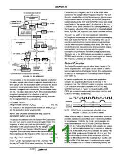
Center Frequency Register, and SOF is the 32-bit value
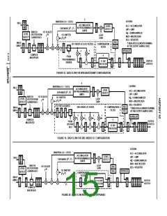
TO DECIMATING FILTERS
loaded into the Sample Offset Frequency Register. The SCF
Register is loaded through the Microprocessor Interface (see
Microprocessor Interface Section), and the SOF Register is
loaded serially via the SOF and SOFSYNC inputs (see Serial
PROGRAMMABLE
DIVIDER
MODE †
SAMPLE PHASE
OUT CONTROL †
SSTRB
SPH0-4
REG
Input Section). The sample rate F is a function of the Input
s
DATARDY
MUX
Controller Mode. If the Controller is in Gated Input Mode, F is
s
the frequency with which ENI is asserted. In Interpolated Input
Mode, F is the CLK frequency (see Input Controller Section).
s
SYNC
CLK
REG
32-BIT ADDER
CARRY OUTPUT
5
The carry out and 5 of the most significant 8 bits of the
NCO’s phase accumulator are output to control a resampling
filter such as the HSP43168. The resampling filter can be
used to provide finer time (symbol phase) resolution than
can be achieved by the sampling clock alone. This may be
needed to improve transmit/receive timing or better, align a
matched filter’s impulse response with the symbol
boundaries of a baseband waveform at high symbol rates.
The carry out of the NCO’s phase accumulator is output on
SSTRB, and a window of 5 of the 8 most significant 8 bits of
the Phase Accumulator are output on SPH0-4.
SHIFTER
8
0
RE-SAMPLER
32
NCO
REG
MUX
LOAD
RESAMPLER
NCO †
+
SOF ENABLE †
MUX
32
32
0
SOF
REG
SCF REG
SYNC
Output Formatter
SOFSYNC
SOF
SYNC
SHIFT REG
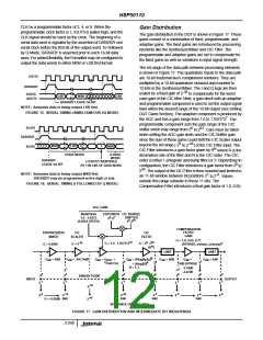
The Output Formatter supports either Word Parallel or Bit
Serial output modes. The output can be chosen to have a
two’s complement or offset binary format. The configuration
is selected by loading the I/O Formatting/Control Register
(see Table 10).
SAMPLER
CENTER
FREQUENCY †
LOAD
ON CF
WRITE
† Controlled via microprocessor interface.
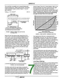
FIGURE 13. RE-SAMPLER
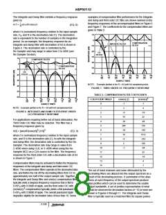
In parallel output mode, the in-phase and quadrature
samples are output simultaneously at rates up to the
maximum CLK. The DATARDY output is asserted on the first
CLK cycle that new data is available on IOUT0-9 and
QOUT0-9 as shown in Figure 14. Output enables (OEI,
OEQ) are provided to individually three-state IOUT0-9 and
QOUT0-9 for output multiplexing.
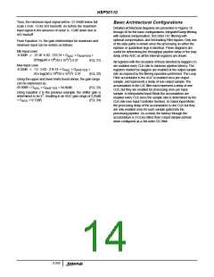
The calculation of the decimation factor depends on whether
the output sample rate is fixed or adjusted dynamically. For a
fixed sample rate, the decimation factor is equal to the divisor
loaded into the programmable divider. For example, if the
divider is configured with a divisor of 8, the decimation factor
is 8 (i.e., the output data rate is F /8). If the decimation factor
s
is adjusted dynamically, it is a function of both the
programmable divisor and the frequency of carry outs from
the Re-Sampler NCO (F ) as given by:
CO
CLK
DATARDY
Decimation Factor =
(Programmable Divisor) x F /F
(EQ. 10)
IOUT9-0/
QOUT9-0
s
CO
For example, if the programmable divisor is 8 and F /F
s
=
CO
NOTE: DATARDY may be programmed active high or low.
40, the decimation factor would be 320.
FIGURE 14. PARALLEL OUTPUT TIMING
NOTE: The CIC filter architecture only supports
decimation factors up to 4096.
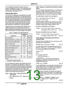
When bit serial output is chosen, two serial output modes are
provided, Simultaneous I/Q Mode and I Followed by Q Mode.
In Simultaneous I/Q Mode, the 10-bit I and Q samples are
output simultaneously on IOUT0 and QOUT0 as shown in
Figure 15. In I Followed by Q Mode, both samples are output
on IOUT0 with I samples followed by Q samples as shown in
Figure 16. In this mode, the I and Q samples are packed into
separate 16-bit serial words (10 data bits + 6 zero bits). The
10 data bits are the 10 MSBs of the serial word, and the I
sample is differentiated from the Q sample by a 1 in the LSB
position of the 16-bit data word. A continuous serial output
clock is provided on IOUT9 which is derived by dividing the
The phase accumulator in the Re-Sampler NCO generates
the carry outs used to clock the programmable divider. The
frequency at which carry outs are generated (F ) is
CO
determined by the values loaded into the Sampler Center
Frequency (SCF) and Sampler Offset Frequency (SOF)
Registers. The relationship between the values loaded into
these registers and the frequency of the carry outs is given by:
F
= F x (SCF + SOF)/232
(EQ. 11)
CO
s
where F is the input sample rate of the Low Pass Filter
s
Section, SCF is the 32-bit value loaded into the Sampler
3-239

 INTERSIL [ Intersil ]