HSP50110
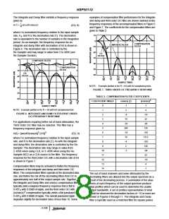
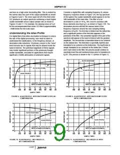
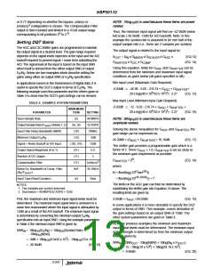
and less as a high order decimating filter. This is evident by
Consider a digital filter with sampling frequency fs, whose
frequency response shown in Figure 12A, the top spectrum.
At first glance the usable bandwidth would appear to be the
3dB bandwidth of the main lobe. This filter is to be
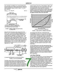
the narrow alias free part of the output bandwidth as shown
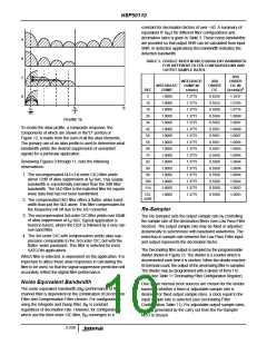
in Figures 8 and 9. The more rapid roll off of the third order
CIC produces an output spectrum containing a much higher
usable bandwidth versus output sample rate as shown in
decimated to a rate of 1/8 f . We concern ourselves with
S
Figures 10 and 11. For example, the aliasing noise at F /4
those elements less than f /2, as shown in Figure 12B. The
S
S
for the uncompensated third order CIC filter is approximately
~29dB below the full scale input.
decimation process will fold the various lobes of the
frequency response around the new sampling folding
frequency of f /2R. The first lobe is folded over the dotted line
S
Understanding the Alias Profile
and a significant portion of the first lobe appears in the
passband of the filter. Any unwanted signals in this part of the
spectrum will appear in the band of interest with the greatest
amplitude. The second lobe is translated down to be centered
on the dashed line. The third lobe is spectrally inverted and
translated to be centered on the dotted line. The fourth lobe is
simply translated to be centered on the dotted line. If there
were more lobes to the filter, the process would continue to
spectrally invert the odd numbered lobes prior to translation to
For digital filters that utilize decimation techniques to reduce
the rate of the digital processing, care must be taken to
understand the ramifications, in the frequency domain, of
decimation (rate reduction). Of primary concern is the “noise”
level increase due to signals that may be aliased inside the
band of interest. The potential magnitude of these signals
may render significant portions of the previously thought
usable bandwidth, unusable for applications that require
significant (>60dB) attenuation of undesired signals.
f /2R. This process is shown in the “C” portion of Figure 12.
S
10
10
0
FILTER RESPONSE
0
-10
-10
FILTER RESPONSE
ALIAS PROFILE
-20
-20
ALIAS PROFILE
-30
-30
-40
-40
-50
-60
-50
-60
(EXAMPLE PLOTTED IS FOR R = 64
WITH 64 SAMPLES/SYMBOL)
(EXAMPLE PLOTTED IS FOR R = 64
WITH 64 SAMPLES/SYMBOL)
0
0
f
f
3f
f
5f
3f
7f
f
f
f
3f
f
5f
3f
7f
f
S
S
S
S
S
S
S
S
S
S
S
S
S
S
S
S
16R
8R
16R
4R
16R
8R
16R
2R
16R
8R
16R
4R
16R
8R
16R
2R
SAMPLE TIMES
SAMPLE TIMES
FIGURE 8. ALIAS PROFILE: INTEGRATE/DUMP FILTER, NO
COMPENSATION
FIGURE 9. ALIAS PROFILE: INTEGRATE/DUMP FILTER
WITH COMPENSATION
10
0
10
0
FILTER RESPONSE
-10
-10
-20
-30
-40
-50
-60
FILTER RESPONSE
-20
-30
ALIAS PROFILE
ALIAS PROFILE
-40
-50
-60
(EXAMPLE PLOTTED IS FOR R = 64
WITH 64 SAMPLES/SYMBOL)
(EXAMPLE PLOTTED IS FOR R = 64
WITH 64 SAMPLES/SYMBOL)
0
0
f
f
3f
f
5f
3f
7f
f
f
f
3f
f
5f
3f
7f
f
S
S
S
S
S
S
S
S
S
S
S
S
S
S
S
S
16R
8R
16R
4R
16R
8R
16R
2R
16R
8R
16R
4R
16R
8R
16R
2R
SAMPLE TIMES
SAMPLE TIMES
FIGURE 10. ALIAS PROFILE: 3RD ORDER CIC,
NO COMPENSATION
FIGURE 11. ALIAS PROFILE: 3RD ORDER CIC WITH
COMPENSATION
3-237

 INTERSIL [ Intersil ]