®
MOBILE PENTIUM PROCESSOR WITH MMX™ TECHNOLOGY
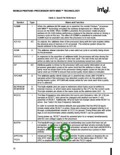
Table 4. Quick Pin Reference (Contd.)
Name and Function
Symbol
HOLD
Type
I
In response to the bus hold request, the processor will float most of its output
and input/output pins and assert HLDA after completing all outstanding bus
cycles. The processor will maintain its bus in this state until HOLD is de-asserted.
HOLD is not recognized during LOCK cycles. The processor will recognize HOLD
during reset.
IERR#
O
I
The internal error pin is used to indicate internal parity errors. If a parity error
occurs on a read from an internal array, the processor will assert the IERR# pin
for one clock and then shutdown.
IGNNE#
This is the ignore numeric error input. This pin has no effect when the NE bit in
CR0 is set to 1. When the CR0.NE bit is 0, and the IGNNE# pin is asserted, the
processor will ignore any pending unmasked numeric exception and continue
executing floating-point instructions for the entire duration that this pin is
asserted. When the CR0.NE bit is 0, IGNNE# is not asserted, a pending
unmasked numeric exception exists (SW.ES = 1), and the floating-point
instruction is one of FINIT, FCLEX, FSTENV, FSAVE, FSTSW, FSTCW, FENI,
FDISI, or FSETPM, the processor will execute the instruction in spite of the
pending exception. When the CR0.NE bit is 0, IGNNE# is not asserted, a pending
unmasked numeric exception exists (SW.ES = 1), and the floating-point
instruction is one other than FINIT, FCLEX, FSTENV, FSAVE, FSTSW, FSTCW,
FENI, FDISI, or FSETPM, the processor will stop execution and wait for an
external interrupt.
INIT
I
I
The processor initialization input pin forces the processor to begin execution in
a known state. The processor state after INIT is the same as the state after
RESET except that the internal caches, write buffers, and floating-point registers
retain the values they had prior to INIT. INIT may NOT be used in lieu of RESET
after power up.
If INIT is sampled high when RESET transitions from high to low, the processor
will perform built-in self test prior to the start of program execution.
INTR
An active maskable interrupt input indicates that an external interrupt has been
generated. If the IF bit in the EFLAGS register is set, the processor will generate
two locked interrupt acknowledge bus cycles and vector to an interrupt handler
after the current instruction execution is completed. INTR must remain active until
the first interrupt acknowledge cycle is generated to assure that the interrupt is
recognized.
INV
I
I
The invalidation input determines the final cache line state (S or I) in case of an
inquire cycle hit. It is sampled together with the address for the inquire cycle in
the clock EADS# is sampled active.
KEN#
The cache enable pin is used to determine whether the current cycle is
cacheable or not and is consequently used to determine cycle length. When the
processor generates a cycle that can be cached (CACHE# asserted) and KEN#
is active, the cycle will be transformed into a burst line fill cycle.
21

 INTEL [ INTEL ]