®
MOBILE PENTIUM PROCESSOR WITH MMX™ TECHNOLOGY
Note
3.3.
Design Notes
All input pins must meet their AC/DC
specifications to guarantee proper functional
behavior.
For reliable operation, always connect unused
inputs to an appropriate signal level. Unused active
low inputs should be connected to VCC3. Unused
active HIGH inputs should be connected to GND
(VSS).
The # symbol at the end of a signal name indicates
that the active or asserted state occurs when the
signal is at a low voltage. When a # symbol is not
present after the signal name, the signal is active,
or asserted at the high voltage level. Square
brackets around a signal name indicate that the
signal is defined only at RESET.
No Connect (NC) pins must remain unconnected.
Connection of NC pins may result in component
failure or incompatibility with processor steppings.
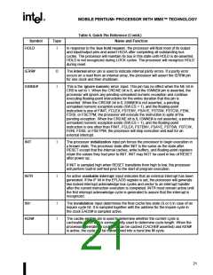
3.4.
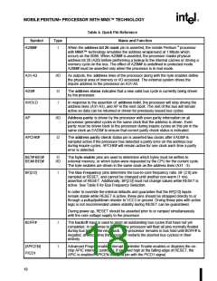
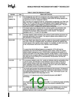
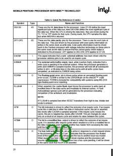
Quick Pin Reference
The pins are classified as Input or Output based on
their function in Master Mode. See the Error
Detection chapter of the Pentium® Processor
Family Developer’s Manual, for further information.
This section gives a brief functional description of
each of the pins. For a detailed description, see the
Hardware Interface chapter in the Pentium®
Processor Family Developer's Manual.
17

 INTEL [ INTEL ]