®
MOBILE PENTIUM PROCESSOR WITH MMX™ TECHNOLOGY
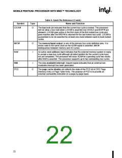
Table 4. Quick Pin Reference (Contd.)
Symbol
LOCK#
Type
Name and Function
O
The bus lock pin indicates that the current bus cycle is locked. The processor
will not allow a bus hold when LOCK# is asserted (but AHOLD and BOFF# are
allowed). LOCK# goes active in the first clock of the first locked bus cycle and
goes inactive after the BRDY# is returned for the last locked bus cycle. LOCK# is
guaranteed to be de-asserted for at least one clock between back-to-back locked
cycles.
M/IO#
NA#
O
I
The memory/input-output is one of the primary bus cycle definition pins. It is
driven valid in the same clock as the ADS# signal is asserted. M/IO#
distinguishes between memory and I/O cycles.
An active next address input indicates that the external memory system is ready
to accept a new bus cycle although all data transfers for the current cycle have
not yet completed. The processor will issue ADS# for a pending cycle two clocks
after NA# is asserted. The processor supports up to two outstanding bus cycles.
NMI
I
The non-maskable interrupt request signal indicates that an external non-
maskable interrupt has been generated.
PCD
O
The page cache disable pin reflects the state of the PCD bit in CR3; Page
Directory Entry or Page Table Entry. The purpose of PCD is to provide an
external cacheability indication on a page-by-page basis.
22

 INTEL [ INTEL ]