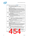
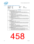
LPC Interface Bridge Registers (D31:F0)
Bit
Description
SLP_S4# Assertion Stretch Enable — R/W.
0 = The SLP_S4# minimum assertion time is 1 to 2 RTCCLK.
1 = The SLP_S4# signal minimally assert for the time specified in bits 5:4 of this
register.
3
This bit is cleared by RTCRST#.
NOTE: This bit is RO when the SLP_S4# Stretching Policy Lock-Down bit is set.
RTC Power Status (RTC_PWR_STS) — R/W. This bit is set when RTCRST#
indicates a weak or missing battery. The bit is not cleared by any type of reset. The
bit will remain set until the software clears it by writing a 0 back to this bit position.
2
Power Failure (PWR_FLR) — R/WC. This bit is in the SUS well, and defaults to a
‘1’ based on RSMRST# assertion (not cleared by any type of reset).
1
0 = Indicates that the trickle current has not failed since the last time the bit was
cleared. Software clears this bit by writing a 1 to it.
1 = Indicates that the trickle current (from the main battery or trickle supply) was
removed or failed.
(Corporate
Only)
Power Failure (PWR_FLR) — R/WC. This bit is in the RTC well, and is not
cleared by any type of reset except RTCRST#.
0 = Indicates that the trickle current has not failed since the last time the bit was
cleared. Software clears this bit by writing a 1 to it.
1 = Indicates that the trickle current (from the main battery or trickle supply) was
removed or failed.
1
(Consumer
Only)
NOTE: Clearing CMOS in an ICH-based platform can be done by using a jumper on
RTCRST# or GPI, or using SAFEMODE strap. Implementations should not
attempt to clear CMOS by using a jumper to pull VccRTC low.
AFTERG3_EN — R/W. This bit determines what state to go to when power is re-
applied after a power failure (G3 state).
0 = System will return to S0 state (boot) after power is re-applied.
1 = System will return to the S5 state (except if it was in S4, in which case it will
return to S4).
0
(Corporate
Only)
In the S5 state, the only enabled wake event is the Power Button or any enabled
wake event that was preserved through the power failure.
This bit is cleared by RTCRST#.
AFTERG3_EN — R/W. This bit determines what state to go to when power is re-
applied after a power failure (G3 state). This bit is in the RTC well and is only
cleared by writes of 06h or 0Eh to CF9h (when the CF9h global reset bit is clear),
receiving hard reset command with or without power cycle from SMBus or
RTCRST#.
0 = System will return to S0 state (boot) after power is re-applied.
1 = System will return to the S5 state (except if it was in S4, in which case it will
return to S4). In the S5 state, the only enabled wake event is the Power
Button or any enabled wake event that was preserved through the power
failure.
0
(Consumer
Only)
NOTE: This bit is set any time a Power Button Override occurs (i.e., the power
button is pressed for at least 4 consecutive seconds), due to the
corresponding bit in the SMBus unconditional power down message, due to
an internal thermal sensor catastrophic condition and the assertion of
THRMTRIP#.
NOTE: RSMRST# is sampled using the RTC clock. Therefore, low times that are less than one RTC
clock period may not be detected by the ICH10.
454
Datasheet

 INTEL [ INTEL ]