LPC Interface Bridge Registers (D31:F0)
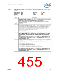
Bit
Description
Minimum SLP_S4# Assertion Width Violation Status — R/WC.
0 = Software clears this bit by writing a 1 to it.
1 = Hardware sets this bit when the SLP_S4# assertion width is less than the time
programmed in the SLP_S4# Minimum Assertion Width field (D31:F0:Offset
A4h:bits 5:4). The ICH10 begins the timer when SLP_S4# is asserted during S4/S5
entry, or when the RSMRST# input is deasserted during G3 exit. Note that this bit
is functional regardless of the value in the SLP_S4# Assertion Stretch Enable
(D31:F0:Offset A4h:bit 3).
2
NOTE: This bit is reset by the assertion of the RSMRST# pin, but can be set in some
cases before the default value is readable.
CPU Power Failure (CPUPWR_FLR) — R/W.
0 = Software (typically BIOS) clears this bit by writing a 0 to it.
1 = Indicates that the VRMPWRGD signal from the processor’s VRM went low while the
system was in an S0 or S1 state.
NOTE: VRMPWRGD is sampled using the RTC clock. Therefore, low times that are less
than one RTC clock period may not be detected by the Intel ICH10.
1
0
PWROK Failure (PWROK_FLR) — R/WC.
0 = Software clears this bit by writing a 1 to it, or when the system goes into a G3
state.
1 = This bit will be set any time PWROK goes low, when the system was in S0, or S1
state. The bit will be cleared only by software by writing a 1 to this bit or when the
system goes to a G3 state.
NOTE: See Chapter 5.13.6.3 for more details about the PWROK pin functionality.
NOTE: In the case of true PWROK failure, PWROK will go low first before the
VRMPWRGD.
Datasheet
451

 INTEL [ INTEL ]