DRAM Controller Registers (D0:F0)
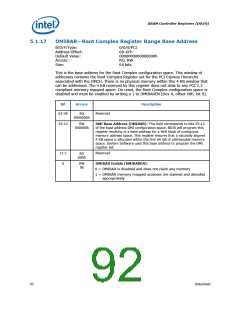
5.1.14
GGC—GMCH Graphics Control
B/D/F/Type:
Address Offset:
Default Value:
Access:
0/0/0/PCI
52–53h
0030h
RO, RW/L
16 bits
Size:
Bit
15:7
6:4
Access &
Description
Default
RO
00h
Reserved
RW/L
011b
Graphics Mode Select (GMS): This field is used to select the
amount of Main Memory that is pre-allocated to support the Internal
Graphics device in VGA (non-linear) and Native (linear) modes. The
BIOS ensures that memory is pre-allocated only when Internal
graphics is enabled.
000 =
No memory pre-allocated. Device 2 (IGD) does not claim
VGA cycles (Memory and I/O), and the Sub-Class Code field
within Device 2, function 0, Class Code register is 80h.
001 =
DVMT (UMA) mode, 1 MB of memory pre-allocated for
frame buffer.
010 =
011 =
Reserved
DVMT (UMA) mode, 8 MB of memory pre-allocated for
frame buffer.
100 =
101 =
110 =
111 =
Reserved
Reserved
Reserved
Reserved
Note: This register is locked and becomes Read Only when the
D_LCK bit in the SMRAM register is set.
BIOS Requirement: BIOS must not set this field to 000 if IVD (bit 1
of this register) is 0.
3:2
1
RO
00b
Reserved
RW/L
0b
IGD VGA Disable (IVD):
0 =Enable. Device 2 (IGD) claims VGA memory and I/O cycles, the
Sub-Class Code within Device 2 Class Code register is 00h.
1 =Disable. Device 2 (IGD) does not claim VGA cycles (Memory and
I/O), and the Sub-Class Code field within Device 2, function 0
Class Code register is 80h.
0
RO
0b
Reserved
88
Datasheet

 INTEL [ INTEL ]