DRAM Controller Registers (D0:F0)
5.2.50
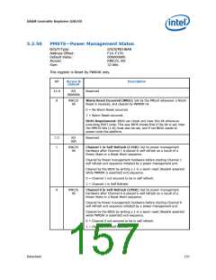
PMSTS—Power Management Status
B/D/F/Type:
Address Offset:
Default Value:
Access:
0/0/0/MCHBAR
F14–F17h
00000000h
RWC/S, RO
32 bits
Size:
This register is Reset by PWROK only.
Bit
31:9
8
Access &
Default
Description
RO
000000h
Reserved
RWC/S
0b
Warm Reset Occurred (WRO): Set by the PMunit whenever a Warm
Reset is received, and cleared by PWROK=0.
0 = No Warm Reset occurred.
1 = Warm Reset occurred.
BIOS Requirement: BIOS can check and clear this bit whenever
executing POST code. This way BIOS knows that if the bit is set, then
the PMSTS bits [1:0] must also be set, and if not BIOS needs to
power-cycle the platform.
7:2
1
RO
00h
Reserved
RWC/S
0b
Channel 1 in Self-Refresh (C1SR): Set by power management
hardware after Channel 1 is placed in self refresh as a result of a
Power State or a Reset Warn sequence.
Cleared by Power management hardware before starting Channel 1
self refresh exit sequence initiated by a power management exit.
Cleared by the BIOS by writing a 1 in a warm reset (Reset# asserted
while PWROK is asserted) exit sequence.
0 = Channel 1 not ensured to be in self refresh.
1 = Channel 1 in Self Refresh.
0
RWC/S
0b
Channel 0 in Self-Refresh (C0SR): Set by power management
hardware after Channel 0 is placed in self refresh as a result of a
Power State or a Reset Warn sequence.
Cleared by Power management hardware before starting Channel 0
self refresh exit sequence initiated by a power management exit.
Cleared by the BIOS by writing a 1 in a warm reset (Reset# asserted
while PWROK is asserted) exit sequence.
0 = Channel 0 not ensured to be in self refresh.
1 = Channel 0 in Self Refresh.
Datasheet
157

 INTEL [ INTEL ]