DRAM Controller Registers (D0:F0)
5.2.47
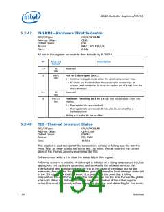
THERM1—Hardware Throttle Control
B/D/F/Type:
Address Offset:
Default Value:
Access:
0/0/0/MCHBAR
CE4h
00h
RW/L, RO, RW/L/K
8 bits
Size:
All bits in this register are reset to their defaults by PLTRST#.
Bit
Access &
Default
Description
7:4
3
RO
00h
Reserved
RW/L
00h
Halt on Catastrophic (HOC):
0 = Continue to toggle clocks when the catastrophic sensor trips.
1 = All clocks are disabled when the catastrophic sensor trips. A
system reset is required to bring the system out of a halt from the
thermal sensor.
2:1
0
RO
00b
Reserved
RW/L/K
00h
Hardware Throttling Lock Bit (HTL): This bit locks bits 7:0 of this
register.
0 = The register bits are unlocked.
1 = The register bits are locked. It may only be set to a 0 by a
hardware reset.
Writing a 0 to this bit has no effect.
5.2.48
TIS—Thermal Interrupt Status
B/D/F/Type:
Address Offset:
Default Value:
Access:
0/0/0/MCHBAR
CEA–CEBh
0000h
RO, RWC
16 bits
Size:
This register is used to report if the temperature is rising or falling past the Hot Trip
Point. After an SMI# is asserted by the Hot Trip Point, SW can examine the current
state of the thermal zones by examining the TSS.
Software must write a 1 to clear the status bits in this register.
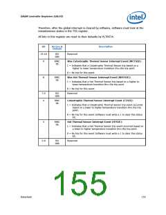
Following scenario is possible. An interrupt is initiated on a rising temperature trip, the
appropriate DMI cycles are generated, and eventually the software services the
interrupt and sees a rising temperature trip as the cause in the status bits for the
interrupts. Assume that the software then goes and clears the local interrupt status bit
in the TIS register for that trip event. It is possible at this point that a falling
temperature trip event occurs before the software has had the time to clear the global
interrupts status bit. But since software has already looked at the status register
before this event happened, software may not clear the local status flag for this event.
154
Datasheet

 INTEL [ INTEL ]