E
INTEL StrataFlash™ MEMORY TECHNOLOGY, 32 AND 64 MBIT
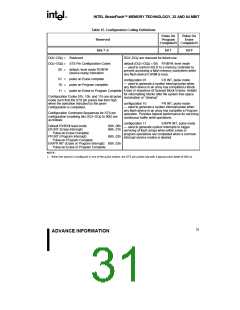
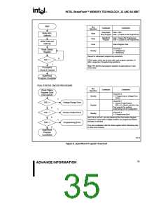
Table 15. Configuration Coding Definitions
Pulse On
Program
Pulse On
Erase
Reserved
Complete(1) Complete(1)
bits 7–2
bit 1
DQ –DQ are reserved for future use.
bit 0
DQ –DQ
=
=
Reserved
STS Pin Configuration Codes
7
2
7
2
DQ –DQ
default (DQ –DQ = 00) RY/BY#, level mode
1 0
1
0
— used to control HOLD to a memory controller to
prevent accessing a flash memory subsystem while
any flash device's WSM is busy.
00 = default, level mode RY/BY#
(device ready) indication
01 = pulse on Erase complete
10 = pulse on Program complete
configuration 01
— used to generate a system interrupt pulse when
any flash device in an array has completed a Block
ER INT, pulse mode
11 = pulse on Erase or Program Complete Erase or sequence of Queued Block Erases. Helpful
for reformatting blocks after file system free space
Configuration Codes 01b, 10b, and 11b are all pulse
reclamation or “cleanup”
mode such that the STS pin pulses low then high
when the operation indicated by the given
configuration is completed.
configuration 10
PR INT, pulse mode
— used to generate a system interrupt pulse when
any flash device in an array has complete a Program
operation. Provides highest performance for servicing
continuous buffer write operations.
Configuration Command Sequences for STS pin
configuration (masking bits DQ –DQ to 00h) are
7
2
as follows:
configuration 11
ER/PR INT, pulse mode
Default RY/BY# level mode:
ER INT (Erase Interrupt):
Pulse-on-Erase Complete
PR INT (Program Interrupt):
B8h, 00h
B8h, 01h
— used to generate system interrupts to trigger
servicing of flash arrays when either erase or
program operations are completed when a common
interrupt service routine is desired.
B8h, 02h
Pulse-on-Program Complete
ER/PR INT (Erase or Program Interrupt): B8h, 03h
Pulse-on-Erase or Program Complete
NOTE:
1. When the device is configured in one of the pulse modes, the STS pin pulses low with a typical pulse width of 250 ns.
31
ADVANCE INFORMATION

 INTEL [ INTEL ]