E
INTEL StrataFlash™ MEMORY TECHNOLOGY, 32 AND 64 MBIT
then takes over, controlling the program and
program verify algorithms internally. After the
program sequence is written, the device
automatically outputs status register data when
read (see Figure 8). The CPU can detect the
completion of the program event by analyzing the
STS pin or status register bit SR.7.
An invalid configuration code will result in both
status register bits SR.4 and SR.5 being set to “1.”
When configured in one of the pulse modes, the
STS pin pulses low with a typical pulse width of
250 ns.
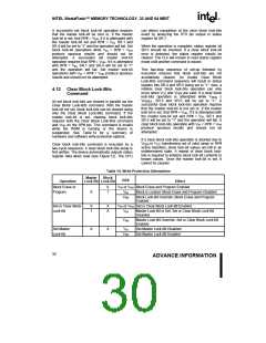
4.11 Set Block and Master Lock-Bit
Commands
When program is complete, status register bit SR.4
should be checked. If a program error is detected,
the status register should be cleared. The internal
WSM verify only detects errors for “1”s that do not
successfully program to “0”s. The CUI remains in
read status register mode until it receives another
command.
A flexible block locking and unlocking scheme is
enabled via a combination of block lock-bits and a
master lock-bit. The block lock-bits gate program
and erase operations while the master lock-bit
gates block-lock bit modification. With the master
lock-bit not set, individual block lock-bits can be set
using the Set Block Lock-Bit command. The Set
Master Lock-Bit command, in conjunction with
RP# = VHH, sets the master lock-bit. After the
master lock-bit is set, subsequent setting of block
lock-bits requires both the Set Block Lock-Bit
command and VHH on the RP# pin. These
commands are invalid while the WSM is running or
Reliable byte/word programs can only occur when
VCC and VPEN are valid. If a byte/word program is
attempted while VPEN ≤ VPENLK, status register bits
SR.4 and SR.3 will be set to “1.” Successful
byte/word programs require that the corresponding
block lock-bit be cleared or, if set, that RP# = VHH
.
If a byte/word program is attempted when the
corresponding block lock-bit is set and RP# = VIH,
SR.1 and SR.4 will be set to “1.” Byte/Word
program operations with VIH < RP# < VHH produce
spurious results and should not be attempted.
the device is suspended. See Table 14 for
summary of hardware and software write protection
options.
a
Set block lock-bit and master lock-bit commands
are executed by a two-cycle sequence. The set
block or master lock-bit setup along with
appropriate block or device address is written
followed by either the set block lock-bit confirm (and
an address within the block to be locked) or the set
master lock-bit confirm (and any device address).
The WSM then controls the set lock-bit algorithm.
After the sequence is written, the device
automatically outputs status register data when
read (see Figure 11). The CPU can detect the
completion of the set lock-bit event by analyzing the
STS pin output or status register bit SR.7.
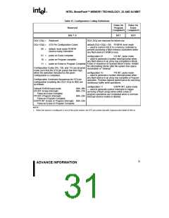
4.10 Configuration Command
The Status (STS) pin can be configured to different
states using the Configuration command. Once the
STS pin has been configured, it remains in that
configuration until another configuration command
is issued or RP# is asserted low. Initially, the STS
pin defaults to RY/BY# operation where RY/BY#
low indicates that the state machine is busy.
RY/BY# high indicates that the state machine is
ready for a new operation or suspended. Table 15
displays the possible STS configurations.
When the set lock-bit operation is complete, status
register bit SR.4 should be checked. If an error is
detected, the status register should be cleared. The
CUI will remain in read status register mode until a
new command is issued.
To reconfigure the Status (STS) pin to other modes,
the Configuration command is given followed by the
desired configuration code. The three alternate
configurations are all pulse mode for use as a
system interrupt as described below. For these
configurations, bit
interrupt pulse, and bit
0
controls Erase Complete
controls Program
This two-step sequence of set-up followed by
execution ensures that lock-bits are not accidentally
set. An invalid Set Block or Master Lock-Bit
command will result in status register bits SR.4 and
SR.5 being set to “1.” Also, reliable operations
occur only when VCC and VPEN are valid. With VPEN
≤ VPENLK, lock-bit contents are protected against
alteration.
1
Complete interrupt pulse. Supplying the 00h
configuration code with the Configuration command
resets the STS pin to the default RY/BY# level
mode. The possible configurations and their usage
are described in Table 15. The Configuration
command may only be given when the device is not
busy or suspended. Check SR.7 for device status.
29
ADVANCE INFORMATION

 INTEL [ INTEL ]