E
INTEL StrataFlash™ MEMORY TECHNOLOGY, 32 AND 64 MBIT
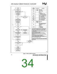
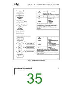
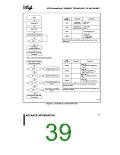
Start
Bus
Operation
Command
Comments
Setup Byte/
Data = 40H
Write 40H,
Address
Write
Word Program Addr = Location to Be Programmed
Byte/Word
Program
Data = Data to Be Programmed
Addr = Location to Be Programmed
Write
Read
Write Data and
Address
Status Register Data
Check SR.7
1 = WSM Ready
0 = WSM Busy
Read Status
Register
Standby
Repeat for subsequent programming operations.
0
SR.7 =
1
SR full status check can be done after each program operation, or
after a sequence of programming operations.
Write FFH after the last program operation to place device in read
array mode.
Full Status
Check if Desired
Byte/Word
Program Complete
FULL STATUS CHECK PROCEDURE
Bus
Operation
Command
Comments
Check SR.3
1 = Programming to Voltage Error
Detect
Read Status
Register Data
(See Above)
Standby
1
Check SR.1
SR.3 =
SR.1 =
SR.4 =
Voltage Range Error
1 = Device Protect Detect
RP# = VIH, Block Lock-Bit Is Set
Only required for systems
implemeting lock-bit configuration.
Standby
Standby
0
0
0
1
1
Check SR.4
1 = Programming Error
Device Protect Error
Programming Error
SR.4, SR.3 and SR.1 are only cleared by the Clear Status Register
command in cases where multiple locations are programmed before
full status is checked.
If an error is detected, clear the status register before attempting retry
or other error recovery.
Byte/Word
Program
Successful
0606_08
Figure 8. Byte/Word Program Flowchart
35
ADVANCE INFORMATION

 INTEL [ INTEL ]