INTEL StrataFlash™ MEMORY TECHNOLOGY, 32 AND 64 MBIT
E
A successful set block lock-bit operation requires
that the master lock-bit be zero or, if the master
lock-bit is set, that RP# = VHH. If it is attempted with
the master lock-bit set and RP# = VIH, SR.1 and
SR.4 will be set to “1” and the operation will fail. Set
block lock-bit operations while VIH < RP# < VHH
produce spurious results and should not be
can detect completion of the clear block lock-bits
event by analyzing the STS pin output or status
register bit SR.7.
When the operation is complete, status register bit
SR.5 should be checked. If a clear block lock-bit
error is detected, the status register should be
cleared. The CUI will remain in read status register
mode until another command is issued.
attempted.
A
successful set master lock-bit
operation requires that RP# = VHH. If it is attempted
with RP# = VIH, SR.1 and SR.4 will be set to “1”
and the operation will fail. Set master lock-bit
operations with VIH < RP# < VHH produce spurious
results and should not be attempted.
This two-step sequence of set-up followed by
execution ensures that block lock-bits are not
accidentally cleared. An invalid Clear Block
Lock-Bits command sequence will result in status
register bits SR.4 and SR.5 being set to “1.” Also, a
reliable clear block lock-bits operation can only
occur when VCC and VPEN are valid. If a clear block
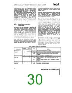
4.12 Clear Block Lock-Bits
Command
lock-bits operation is attempted while VPEN
≤
V
PENLK, SR.3 and SR.5 will be set to “1.” A
All set block lock-bits are cleared in parallel via the
Clear Block Lock-Bits command. With the master
lock-bit not set, block lock-bits can be cleared using
only the Clear Block Lock-Bits command. If the
master lock-bit is set, clearing block lock-bits
requires both the Clear Block Lock-Bits command
and VHH on the RP# pin. This command is invalid
while the WSM is running or the device is
successful clear block lock-bits operation requires
that the master lock-bit is not set or, if the master
lock-bit is set, that RP# = VHH. If it is attempted with
the master lock-bit set and RP# = VIH, SR.1 and
SR.5 will be set to “1” and the operation will fail. A
clear block lock-bits operation with VIH < RP# < VHH
produce spurious results and should not be
attempted.
suspended. See Table 14 for
a summary of
hardware and software write protection options.
If a clear block lock-bits operation is aborted due to
V
PEN or VCC transitioning out of valid range or RP#
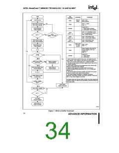
Clear block lock-bits command is executed by a
two-cycle sequence. A clear block lock-bits setup is
first written. The device automatically outputs status
register data when read (see Figure 12). The CPU
active transition, block lock-bit values are left in an
undetermined state. A repeat of clear block lock-
bits is required to initialize block lock-bit contents to
known values. Once the master lock-bit is set, it
cannot be cleared.
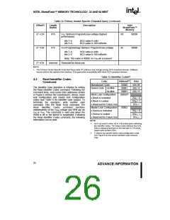
Table 14. Write Protection Alternatives
Block
Master
RP#
Operation
Lock-Bit Lock-Bit
Effect
Block Erase or
Program
0
VIH or VHH Block Erase and Program Enabled
X
1
VIH
Block is Locked. Block Erase and Program Disabled
VHH
Block Lock-Bit Override. Block Erase and Program
Enabled
Set or Clear Block
Lock-Bit
0
1
X
X
VIH or VHH Set or Clear Block Lock-Bit Enabled
VIH
Master Lock-Bit Is Set. Set or Clear Block Lock-Bit
Disabled
VHH
Master Lock-Bit Override. Set or Clear Block Lock-Bit
Enabled
Set Master
Lock-Bit
X
X
VIH
Set Master Lock-Bit Disabled
Set Master Lock-Bit Enabled
VHH
30
ADVANCE INFORMATION

 INTEL [ INTEL ]