INTEL StrataFlash™ MEMORY TECHNOLOGY, 32 AND 64 MBIT
E
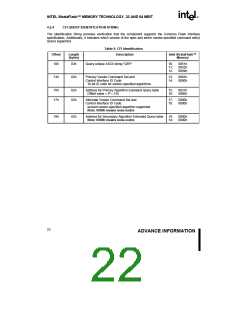
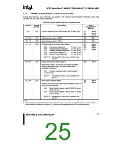
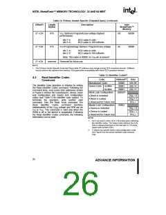
Table 12. Primary Vendor-Specific Extended Query (Continued)
Offset(1)
Length
(bytes)
Description
Intel
StrataFlash™
Memory
(P +C)h
01h
VCC Optimum Program/Erase voltage (highest
performance)
3D:
3E:
0050h
bits 7–4
BCD value in volts
bits 3–0
BCD value in 100 millivolts
(P +D)h
(P +E)h
01h
VPP [Programming] Optimum Program/Erase voltage
0000h
bits 7–4
bits 3–0
HEX value in volts
BCD value in 100 millivolts
Note: This value is 0000h; no VPP pin is present
Reserved for future use
reserved
NOTE:
1. The Primary Vendor-Specific Extended Query table (P) address may change among SCS-compliant devices. Software
should retrieve this address from address 15 to guarantee compatibility with future SCS-compliant devices.
Table 13. Identifier Codes(1)
4.3
Read Identifier Codes
Command
Code
Address(1)
Data
Manufacture Code
Device Code 32-Mbit
64-Mbit
00000
00001
(00) 89
(00) 14
(00) 15
The identifier code operation is initiated by writing
the Read Identifier Codes command. Following the
command write, read cycles from addresses shown
in Figure 6 retrieve the manufacturer, device, block
lock configuration and master lock configuration
codes (see Table 13 for identifier code values). To
terminate the operation, write another valid
command. Like the Read Array command, the
Read Identifier Codes command functions
independently of the VPEN voltage and RP# can be
VIH or VHH. This command is valid only when the
WSM is off or the device is suspended. Following
the Read Identifier Codes command, the following
information can be read:
00001
Block Lock Configuration
• Block Is Unlocked
• Block Is Locked
X0002(2)
DQ0 = 0
DQ0 = 1
DQ1–7
• Reserved for Future Use
Master Lock Configuration
• Device Is Unlocked
• Device Is Locked
• Reserved for Future Use
NOTE:
00003
DQ0 = 0
DQ0 = 1
DQ1–7
1.
A0 is not used in either x8 or x16 modes when obtaining
the identifier codes. The lowest order address line is A .
1
Data is always presented on the low byte in x16 mode
(upper byte contains 00h).
2. X selects the specific block’s lock configuration code.
See Figure 6 for the device identifier code memory
map.
26
ADVANCE INFORMATION

 INTEL [ INTEL ]