Ultra-Low Voltage Intel® Celeron® Processor — 650 MHz and 400 MHz
should consider a discrete resistor to provide the required damping resistance. Too large of a
damping resistance may cause a large IR drop, which means less analog headroom and lower
frequency.
• Ceramic capacitors have very high self-resonance frequencies, but they are not available in
large capacitance values. A high self-resonant frequency coupled with low ESL/ESR is crucial
for sufficient rejection in the PLL and high frequency band. The recommended tantalum
capacitors have acceptably low ESR and ESL.
• The capacitor must be close to the PLL1 and PLL2 pins; otherwise the value of the low ESR
tantalum capacitor is wasted. Note the distance constraint should be translated from the 0.1-Ω
requirement.
3.2.4
Voltage Identification
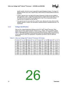
There are five voltage identification balls/pins on the ULV Intel® Celeron® processor. These
signals may be used to support automatic selection of VCC voltages. They are needed to cleanly
support voltage specification variations on current and future processors. VID[4:0] are defined in
Table 10. The VID[4:0] signals are open drain on the processor and need pull-up resistors to 3.3 V
on the motherboard. Refer to the appropriate VR guidelines provided by Intel for additional
information.
Table 10. Ultra-Low Voltage Intel® Celeron® Processor VID Values
VID[4:0]
VCC (V)
VID[4:0]
VCC (V)
VID[4:0]
VCC (V)
VID[4:0]
VCC (V)
00000
00001
00010
00011
00100
00101
00110
00111
1.750
1.700
1.650
1.600
1.550
1.500
1.450
1.400
01000
01001
01010
01011
01100
01101
01110
01111
1.350
1.300
1.250
1.200
1.150
1.100
1.050
1.000
10000
10001
10010
10011
10100
10101
10110
10111
0.975
0.950
0.925
0.900
0.875
0.850
0.825
0.800
11000
11001
11010
11011
11100
11101
11110
11111
0.775
0.750
0.725
0.700
0.675
0.650
0.625
0.600
26
Datasheet

 INTEL [ INTEL ]