Ultra-Low Voltage Intel® Celeron® Processor — 650 MHz and 400 MHz
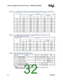
3.2.5.2
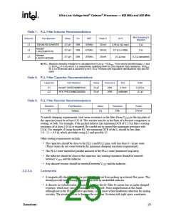
3.2.5.3
Transition Time
The transition time is defined as the time the signal takes to move through the transition region. A
100-µs transition time will ensure that the processor receives a good transition edge.
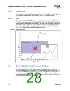
Noise
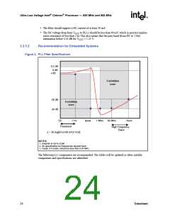
The signal quality of the VTTPWRGD signal is critical to the correct operation of the processor.
Every effort should be made to ensure this signal is monotonic in the transition region. If noise or
glitches are present on this signal, it must be kept to less than 100 mV of a voltage drop from the
highest voltage level received to that point. This glitch must remain less than 100 mV until the
excursion ends by the voltage returning to the highest voltage previously received. Please see
Figure 5 for an example graph of this situation and requirements.
Figure 5. Noise Estimation
3.3
System Bus Clock and Processor Clocking
The BCLK and BCLK# clock inputs directly control the operating speed of the system bus
interface. All system bus timing parameters are specified with respect to the crossing point of the
rising edge of the BCLK input and falling edge of the BCLK# input. The ULV Intel® Celeron®
processor core frequency is a multiple of the BCLK frequency. The processor core frequency is
configured during manufacturing. The configured bus ratio is visible to software in the Power-on
configuration register. See Section 7.2 for details.
28
Datasheet

 INTEL [ INTEL ]