Ultra-Low Voltage Intel® Celeron® Processor — 650 MHz and 400 MHz
3.5
DC Specifications
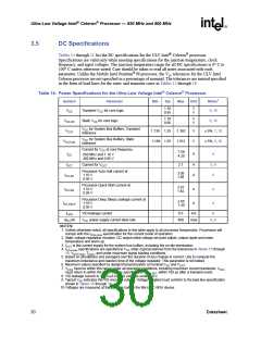
Tables 14 through 21 list the DC specifications for the ULV Intel® Celeron® processor.
Specifications are valid only while meeting specifications for the junction temperature, clock
frequency, and input voltages. The junction temperature range for all DC specifications is 0° C to
100° C unless otherwise noted. Care should be taken to read all notes associated with each
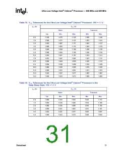
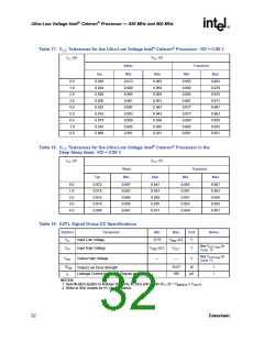
parameter. Unlike the Mobile Intel Pentium® III processor, the Vcc tolerances for the ULV Intel
Celeron processor are not specified as a percentage of nominal. The tolerances are instead specified
in the form of load lines for the static and transient cases in Tables 15 through 18.
Table 14. Power Specifications for the Ultra-Low Voltage Intel® Celeron® Processor
Symbol
Parameter
Min
Typ
Max
Unit
Notes1
1.10
0.95
V
V
VCC
Transient VCC for core logic
9, 10
1.10
0.95
V
V
VCC,DC
VCCT
Static VCC for core logic
9, 10
VCC for System Bus Buffers, Transient
tolerance
1.138 1.25
1.188 1.25
1.362
1.312
V
V
± 9%, 7, 10
± 5%, 2, 10
VCC for System Bus Buffers, Static
tolerance
VCCT,DC
Current for VCC at core frequency
7.58
4.20
ICC
A
4
650 MHz and 1.10 V
400 MHz and 0.95 V
ICCT
Current for VCCT
2.7
A
A
3, 4
4
Processor Auto Halt current at
1.10 V
0.95 V
3.09
1.88
ICC,AH
Processor Quick Start current at
1.10 V
0.95 V
2.91
1.82
ICC,QS
A
A
4
4
Processor Deep Sleep Leakage current at
1.10 V
0.95 V
2.65
1.40
ICC,DSLP
ILVID
dICC/dt
VID leakage current
0.5
mA
8
VCC power supply current slew rate
400
A/µs
5, 6
NOTES:
1. Unless otherwise noted, all specifications in this table apply to all processor frequencies. Processors will
comply with the ICCx max specification for the current mode of operation.
,
2. Static voltage regulation includes: DC output initial voltage set point adjust, output ripple and noise,
temperature and warm up.
3. ICCT is the current supply for the system bus buffers, including the on-die termination.
4. ICCx max
18, VCCT max
,
specifications are specified at VCC static (typical) derived from the tolerances in Tables 15 through
, Tjmax, and under maximum signal loading conditions.
,
5. Based on simulations and averaged over the duration of any change in current. Use to compute the
maximum inductance and reaction time of the voltage regulator. This parameter is not tested.
6. Maximum values specified by design/characterization at nominal VCC and VCCT
7. VCCx must be within this range under all operating conditions, including maximum current transients. VCCx
must return to within the static voltage specification, VCCx DC, within 100 µs after a transient event.
8. VID leakage current is < 100 µA for VID voltages under 3.0 V.
.
,
9. Typical VCC indicates the VID encoded voltage. Voltage supplied must conform to the load line specification
shown in Tables 15 through 18.
10.Voltages are measured at the package ball on the Micro FC-BGA device.
30
Datasheet

 INTEL [ INTEL ]