Ultra-Low Voltage Intel® Celeron® Processor — 650 MHz and 400 MHz
3.2.2
Voltage Planes
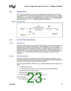
All V and V pins/balls must be connected to the appropriate voltage plane. All V and
CCT
CC
SS
V
pins/balls must be connected to the appropriate traces on the system electronics. In addition
REF
to the main V , V
, and V power supply signals, PLL1 and PLL2 provide analog decoupling
CC
CCT
SS
to the PLL section. PLL1 and PLL2 should be connected according to Figure 2. Do not connect
PLL2 directly to V . Section 3.2.3 contains the RLC filter specification.
SS
Figure 2. PLL RLC Filter
L1
R1
PLL1
PLL2
VCCT
C1
V0027-01
3.2.3
PLL RLC Filter Specification
Introduction
3.2.3.1
All Intel® Celeron® processors have internal PLL clock generators, which are analog in nature and
require quiet power supplies for minimum jitter. Jitter is detrimental to a system; it degrades
external I/O timings as well as internal core timings (i.e. maximum frequency). The PLL RLC filter
specifications for the ULV Intel Celeron processor are the same as those for the mobile Intel
Pentium® III processor-M, and the Mobile Intel Celeron processor. The general desired topology is
shown in Figure 2. Excluded from the external circuitry are parasitics associated with each
component.
3.2.3.2
Filter Specification
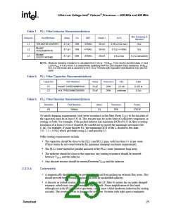
The function of the filter is two fold. It protects the PLL from external noise through low-pass
attenuation. It also protects the PLL from internal noise through high-pass filtering. In general, the
low-pass description forms an adequate description for the filter.
The AC low-pass specification, with input at V
follows:
and output measured across the capacitor, is as
CCT
• < 0.2-dB gain in pass band
• < 0.5-dB attenuation in pass band < 1 Hz (see DC drop in next set of requirements)
• 34-dB attenuation from 1 MHz to 66 MHz
• 28-dB attenuation from 66 MHz to core frequency
• The filter specification (AC) is graphically shown in Figure 3.
Other requirements:
• Use a shielded type inductor to minimize magnetic pickup
Datasheet
23

 INTEL [ INTEL ]